Well, it’s not an attractive radio, but it represents a clever “open source” approach to the problems of expensive tubes, hard-to-find parts, and patent royalties, back in the 1920’s. And it worked surprisingly well. A big question is what can be expected from a radio like this. Restoring this antique answered this question and was an interesting experience.
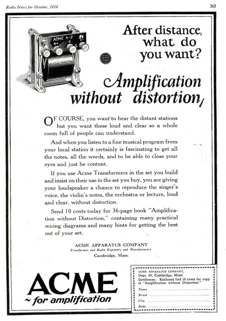
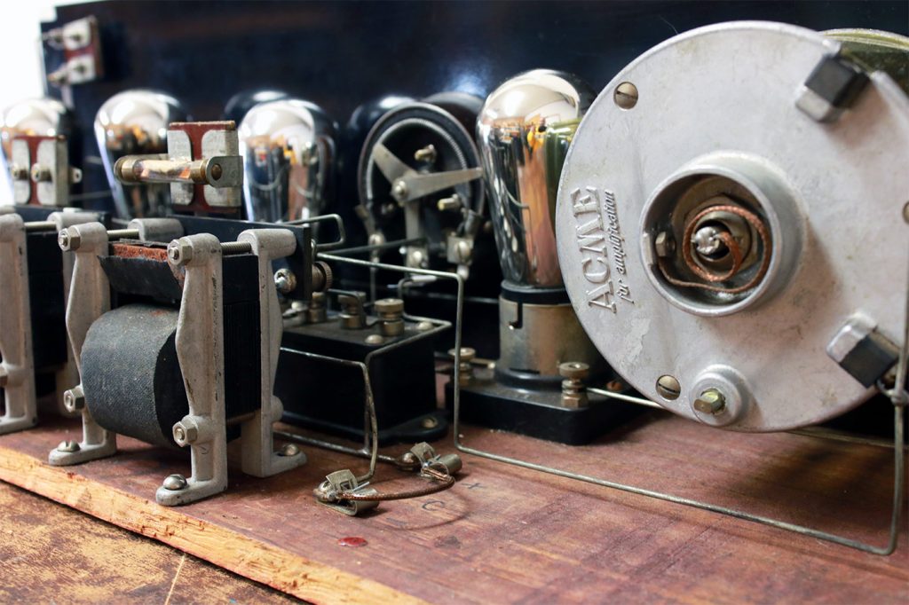
Acme Apparatus Company (Cambridge, MA) specialized in manufacturing radio parts, in particular audio and RF transformers. In that era when tubes only offered low voltage gains of about 5 to 10x, radios used step-up transformers for inter-stage coupling and to step up the voltages. Acme marketed theirs as “Amplification Without Distortion.” Also, Acme evangelized the reflex concept, a design for simultaneously using a tube for both audio and RF gain. That allows a radio to achieve adequate performance with fewer tubes. Prior to this project I was unacquainted with reflex receivers, and the circuit seemed strange until I did some research.
The specific year of this radio is probably 1925. It uses “UX” base tubes, and these were introduced in 1925. Acme advertised frequently in Radio News magazine; advertisements in 1923 and 1924 show most of the components in this example. Several companies sold kits and assembled sets based on the Acme reflex circuit and parts (an ad in the June 1924 issue of Radio News, p. 1722, lists eight such companies). At the pace of radio innovation in those days, I believe that in a year or two this radio would have been obsolete and probably off the market.
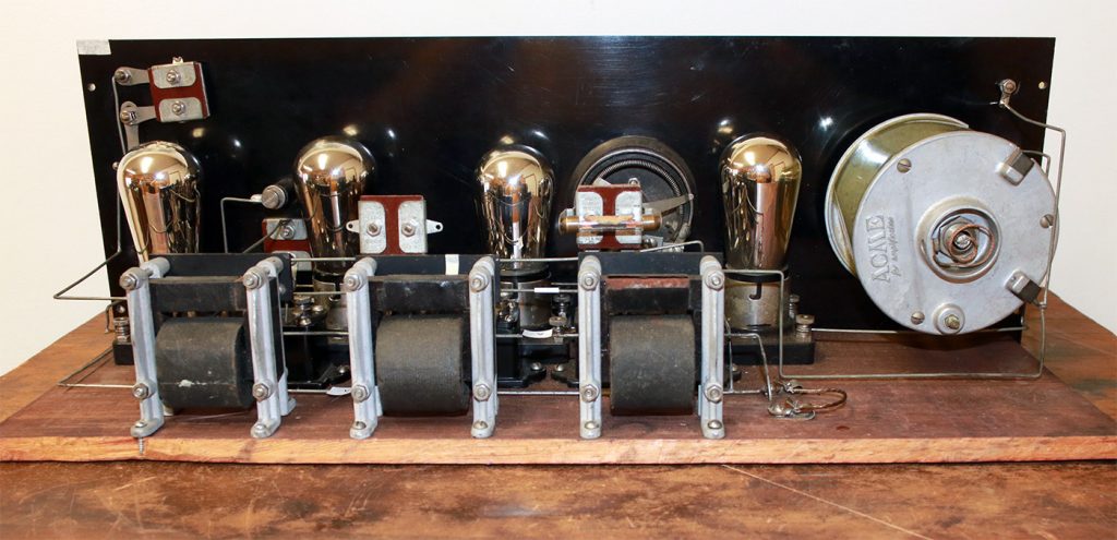
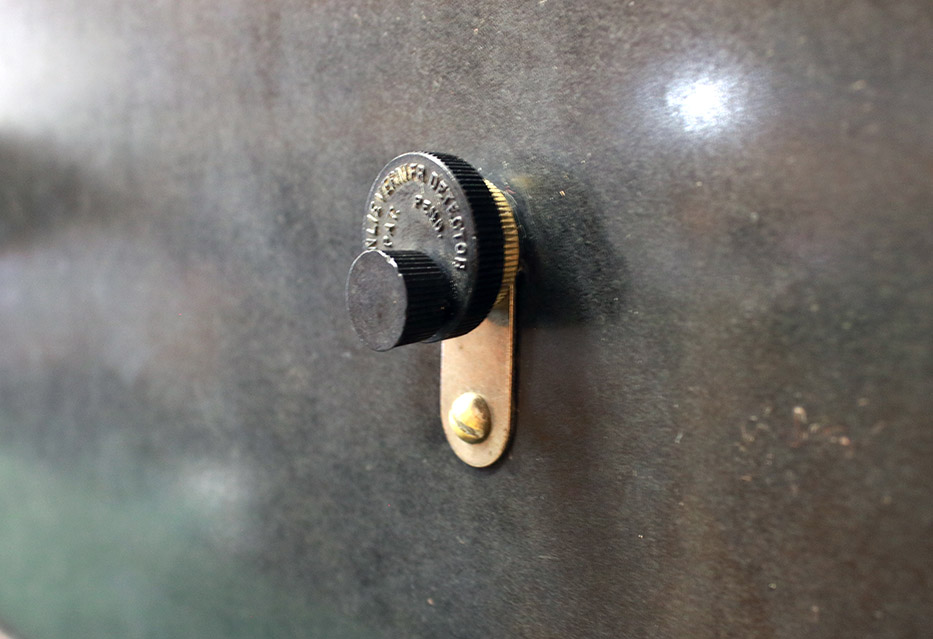
An interesting feature is the panel-mounted detector made by Brownlie Vernier Detector. Instead of the usual arrangement of an arm with a cat whisker, this device has the crystal mounted inside a bakelite cylinder, with the whisker connected to a convenient locking knob with a smaller vernier that makes scratching the crystal much easier. I found that with practice, it could be set for good sound and then just left alone for an evening of listening.
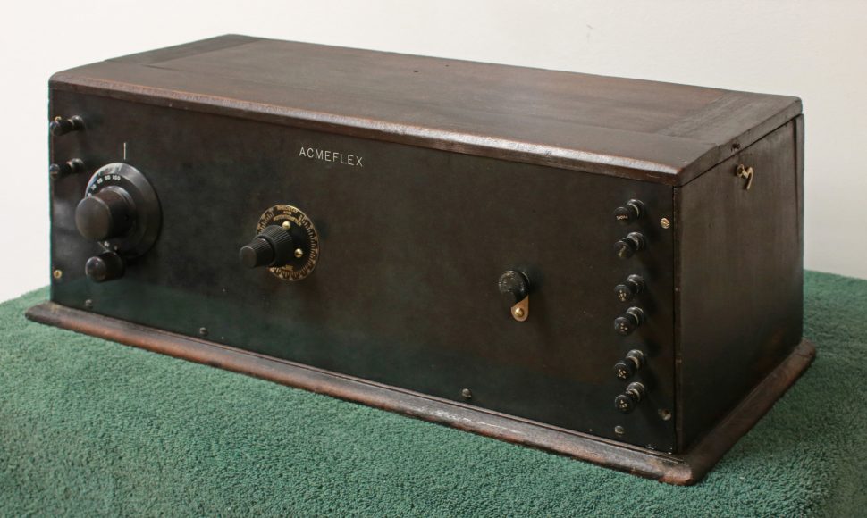
This radio was designed to be inexpensive. It uses 4 tubes to do the work of 6 (but at the cost of more transformers). The crystal detector was less costly than a dedicated tube. The cabinet is a crude pine box, with a bakelite front panel. There is no decoration except for the word ACMEFLEX engraved in a plain font. I estimate this radio could have been sold for $50 (or less) at a time when name-brand, more attractively packaged, 6-tube sets sold for $100 and up.
The Reflex Circuit
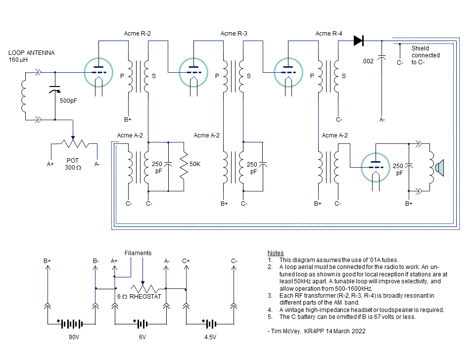
A reflex radio passes the RF signal through one or more gain stages, then after detection, routes the demodulated audio back through the same gain stages. Because each tube is capable of amplification up to a few MHz, and the transformers are built to pass either audio or RF (but not both), fewer tubes are needed. The figure below shows the simplified schematic of this radio.
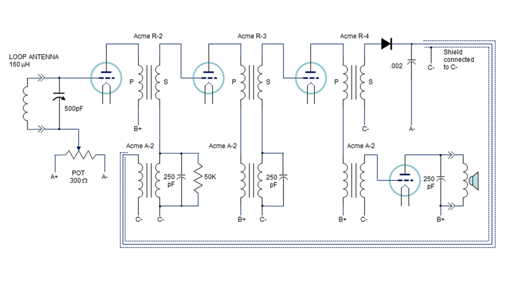
The 1st tube connects directly to the antenna and amplifies the RF signal. The 2nd and 3rd tubes also amplify the RF, and then connect to a crystal detector (represented as a diode for simplicity). The audio from the detector is routed back into the 2nd tube, then the 3rd tube, for amplification. Finally, the 4th tube is the last audio gain stage and connects to a horn speaker.
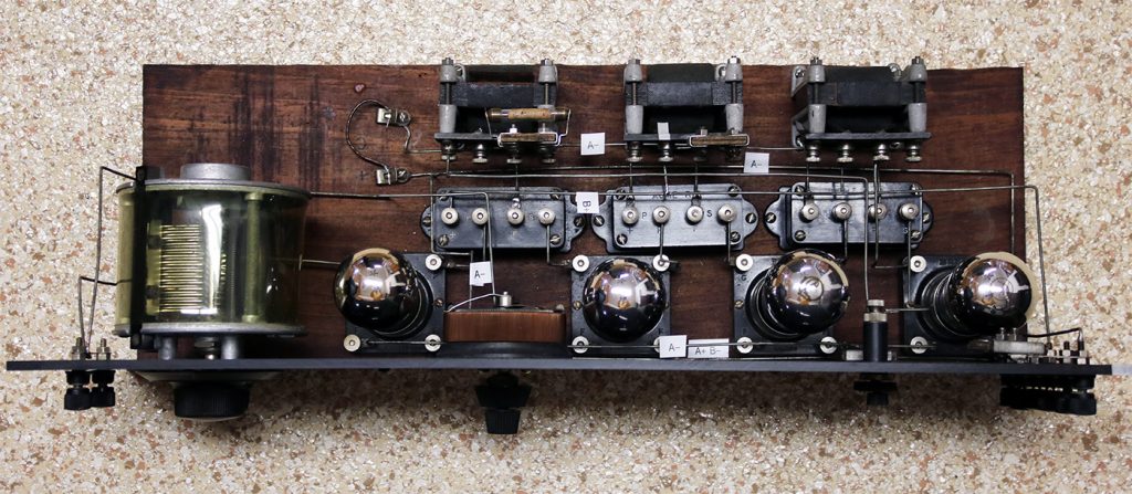
The three RF transformers (Acme parts R-2, R-3, and R-4) are each wound around a flat piece of laminated iron. The primary is wound around the iron (and separated from it by two slivers of wood and a strip of paper), and covered with a paper insulator. The secondary is wound over top of the primary. The entire assembly was put in a bakelite box and filled with beeswax. The difference between R-2, R-3, and R-4 is the broad resonance peak of each, which falls in different parts of the AM broadcast band.
For example, I measured the response of the Acme R-2 “amplifying transformer” with a 1VRMS test signal. Vertical axis is the transformer output in VRMS into a 1M load; horizontal axis is frequency in kHz. The peak is 9.3VRMS at 1480 kHz. The primary DC resistance measured 10.4 ohms and the secondary was 16.4 ohms.
The Acme A-2 transformers are conventional iron-core audio transformers that peak at about 1kHz. Therefore, the response of these transformers, plus the RF traps formed by the capacitors and resistors on their secondaries, suppress positive feedback and circuit instability.
A loop antenna must be connected to complete the first tuned circuit and provide an electrical return for the grid of the 1st tube. A pot varies the grid bias and thus acts as a sensitivity control. The 500pF variable capacitor and a loop inductance of 160mH will tune from 545-1500kHz. But that’s only one tuned stage so the selectivity is poor. However, when this design first came out, it would have worked fine for most people. There were only three broadcast channels, at 360m (833kHz), 485m (618kHz) and 400m (750kHz). After the 10 kHz channel spacing of the AM band was assigned in 1925, a user would need to connect a tuned loop to provide enough selectivity to separate the stations. Acme sold these as an accessory.
Notice there is a rheostat to control all the tube filaments, to adjust volume. Since 3 of the tubes also do RF amplification, turning down the volume also reduces sensitivity. This makes it harder to search for weak stations. Listening through a pair of headphones is a painful experience.
Electrical Restoration
The following steps were completed:
- The variable cap was disassembled and cleaned. In the process of re-assembly the pivots were polished and lubricated, the tension adjusted, and the mechanical stop adjusted. The result was a smooth operating unit with a measured capacity of 3-525 pF.
- The dual pot/rheostat assembly was adjusted, cleaned, and treated with DeOxIt. This unit does not operate perfectly due to a few loose turns on the winding. The rheostat measures 6.2 ohms and the pot measures 220 ohms.
- The glass tube resistor is supposed to be 50k but measures 91k. It works as-is in the circuit, so it was left original.
- All the binding posts were taken out and wire-brushed to remove severe oxidation, cleaned, and treated with DeOxIt.
- Several cold solder joints were repaired.
- There is one connection, for the A- battery, that must have driven people nuts back in the day. If the radio produces a lot of static with just the slightest movement or tapping, it is probably because the soldered A- connection at the back of the binding post is broken. Mechanically this joint is at the pivot of the front panel relative to the breadboard, and breaks easily, creating an intermittent. This is almost invisible, so it took a bit of time to figure it out.
- The R-4 RF transformer secondary was open. It is wound with hair-thin, single strand, cloth covered wire. The connections inside had literally crumbled away. I managed to perform a repair to get it operating, but it will likely fail again. For this reason I did not replace the beeswax. After repair, the primary DCR was 16.4 ohms; the secondary DCR was 26.8 ohms.
- The .002uF mica condenser across the crystal detector measured 1880pF.
- The other two mica condensers measured OK and were left alone.
At first I tested the set using the following voltages: A=6V, B=90V, and C=4.5V. Under these conditions, the best operating point was to set the filament pot for 5V. The C battery provides the grid bias (for the 2nd, 3rd, and 4th tubes) and the AC circuit reference. Thus, varying this voltage makes a difference. Using ‘01A tubes, C at 4.5V worked great, but reducing C to 3.0V caused the radio to not work at all.
Acme said the C battery can be omitted if the B voltage is reduced to 67V or less. Just jumper across the C clips and the set runs fine this way—and it did. However, AC hum is increased by some 20dB, though not enough to be bad to listen to. This means the C battery acts as a bypass capacitor. Imagine: back in the 1920’s if you lived somewhere without electricity, hum would be non-existent!
I found that the unshielded audio loop did not create a feedback problem (unless you touch the wire with your bare finger). However, that loop is likely responsible for picking up AC hum. I did not go to the trouble to attempt shielding it because the original was not shielded.
The first set of tubes I put in the set were very microphonic and swapping them around didn’t completely solve the problem. In the 1920’s, radio users were told to swap tubes for best performance. I put in a set of Philco ST-globe 01A’s and they were great. (The ST shape glass tube envelope was introduced in 1932; one of the reasons tube makers went to ST was to reduce microphonics.) However, I eventually found a set of 1920’s-appropriate balloon-globe tubes that worked fairly well and looked right.
Fortunately the panel-mounted crystal detector still worked. I found it best to pull out and rotate the larger knob in one direction only, until good audio is heard. Then use the fine vernier to improve detection. One can do this by listening for the loudest audio, or by measuring for minimum voltage drop using the diode setting on a VOM. Once the “sweet spot” is found, the crystal can usually be left alone while tuning, and for long periods of listening. Sometimes the volume will suddenly drop and when that happens a light tap to the front will restore the good performance.
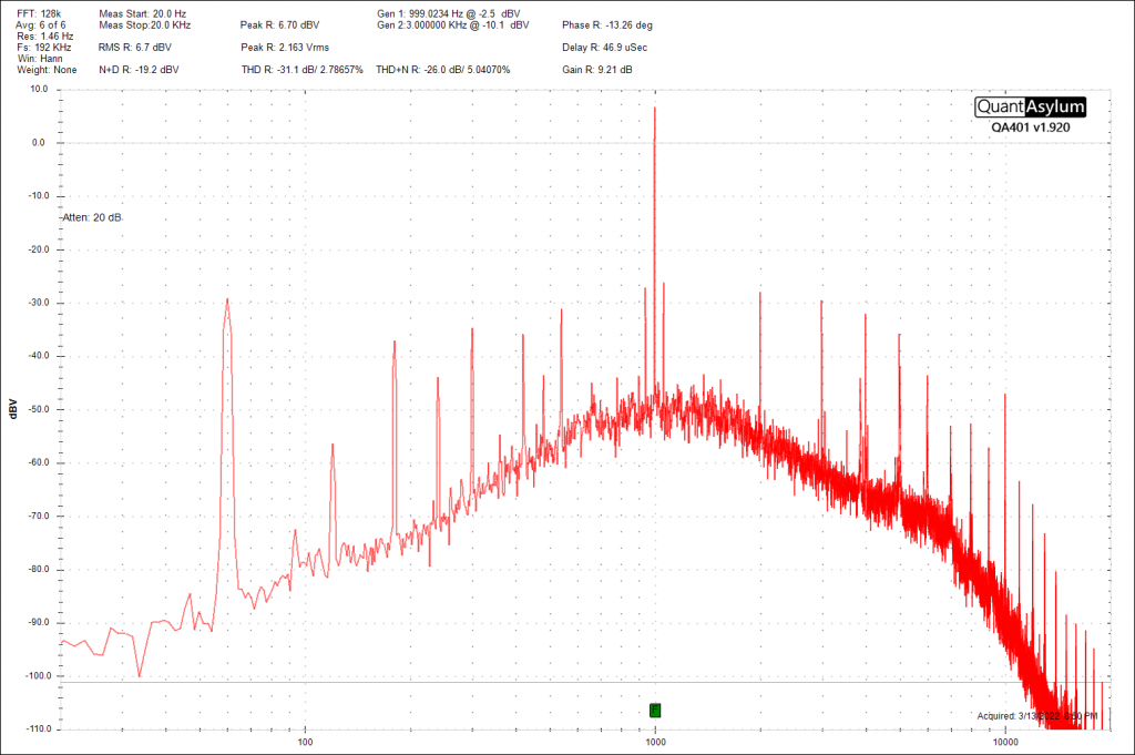
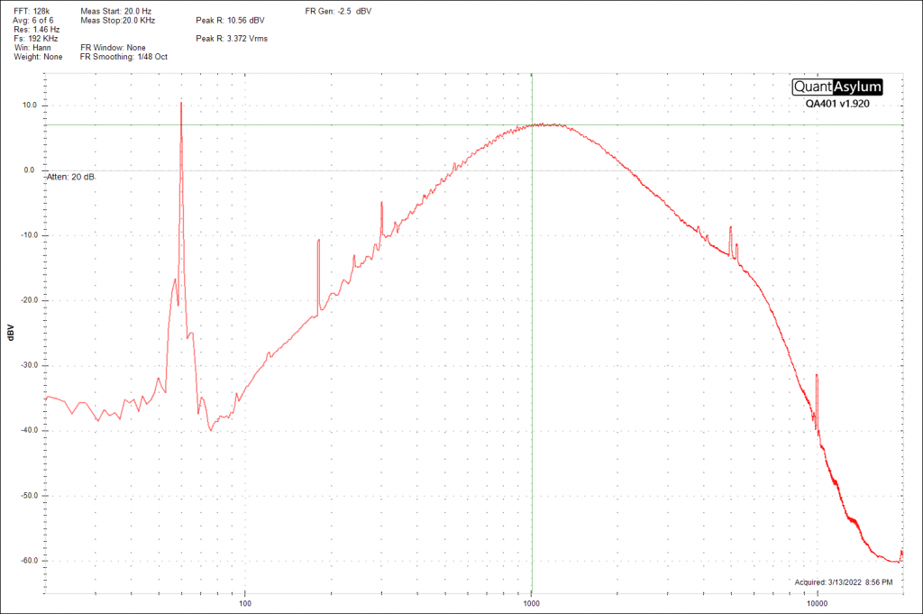
The graph below is an FFT showing the ACMEFLEX response to a 1kHz tone AM-modulated at 25%, coupled to the antenna loop. The input RF signal power, the rheostat + pot on the front panel, and the crystal detector, were all adjusted to find the conditions that produced the lowest distortion. The lowest THD I was able to achieve was a respectable 2.7%. The 60Hz hum is obvious.
Here is an FFT showing the ACMEFLEX overall response to an audio sweep, under the same conditions. It is down 20dB at 250Hz and 5000Hz. (Details of my test setup are available on request.)
To gain some understanding of reception, I connected a tuned loop antenna (see details elsewhere on this website) to the input of the radio. It was possible to tune the loop across the entire AM band with reasonable selectivity. (The tuning dial on the radio provided a very broad match to the loop.) 5 stations were heard during the day, and many clear-channel stations were heard at night. For context, I would normally hear about 20 or so during the day on a modern portable radio.
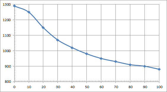
I also tried an outdoor longwire antenna (and earth ground). For this arrangement I used a small air-core transformer wound on a 2.5” diameter form. The primary measured 90uH and the secondary 180uH (59 turns). The secondary was connected to the ACMEFLEX input and the primary to the outdoor antenna. The dial on the radio was able to tune from 1290 to 880kHz (scale 0 to 100). [Note: Acme recommended a 160uH loop.] The graph shows the tuned frequency versus dial setting. Many stations were heard but adjacent channels could not be separated on strong signals.
Conclusion
Here’s a couple of short audio clips. They were captured digitally via a direct electrical connection to the radio, so you can accurately hear what the Acmeflex produces with four ’01A’s and a galena crystal.
This radio is reasonable to use with a 20’s loudspeaker and is sensitive enough to tune in many stations. It took significant effort to acquire the skill to operate the set, and to bring it up to a good level of performance. This was an interesting project and a good learning experience. Best of all, the radio remains all original.
Two references were used in this restoration:
- Reflex Radio Receivers, by P. E. Edelman (publisher: The E. I. Company, New York City, 1924)
- Amplification Without Distortion, 8th Edition, booklet published Feb. 1925 by Acme Apparatus Company
Following is the complete schematic of the Acmeflex radio, exactly as originally wired.
0 Comments