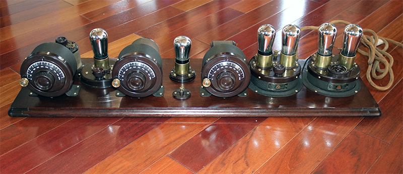
The first Atwater Kent radio sets are fascinating antiques because of their appearance. They were unique in being constructed in a modular fashion without a cabinet. Although there were many companies that sold radio parts and kits of all types in the 1920’s, i think Atwater Kent was possibly the only major company that sold radios like this. AK sold thousands of them until they stopped producing this style in 1926. Today they are iconic radios from those first few years of radio broadcasting, and very sought after by collectors. To me they resemble scientific apparatus…it must have been a curious sight to walk into someone’s home and see one of these.
The Atwater Kent “open” or “breadboard” style radios consisted of modules (collectors call them “islands”), each of which contained the circuitry for a particular function such as an antenna tuner, or an AM detector. These were mounted to a nicely-finished mahogany board. The wires that interconnected the modules passed through holes in the board and ran underneath. Thus, the overall radio looked like a finished, professional product.
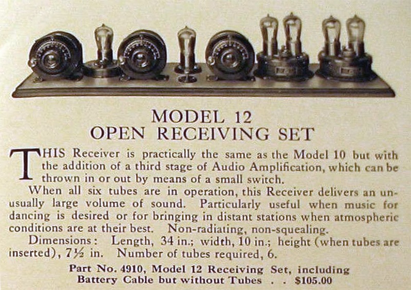
I was asked by the Asheville Radio Museum to assist in the restoration of one of these fascinating radios. This is the model 12 open style (specifically, type 4910) TRF radio. It was the very last “open” or “breadboard” model sold by AK, and was priced at $105 when introduced in late 1925 (equivalent to $1,702 today). Notice the tubes were not included in that price. Nor was the speaker, outdoor antenna, grounding system, batteries, and other radio paraphernalia…
This radio used a #4940 TA Detector-Amplifier module, and a #4925 two tube audio amplifier. It required five type 01A tubes with the UX-style base, and in the detector position either an 01A or 200-A tube could be used.
There were two major efforts made to bring this set back to original, working condition, and retain as much authenticity as possible. Stuart Smolkin at the Asheville Radio Museum performed a significant amount of work to restore the appearance of this set, i.e. the mahogany board was re-finished, the three steel cans were correctly re-finished with brown crinkle paint, all the bakelite parts were cleaned & polished, and all brass parts were cleaned and top-coated with lacquer.
Electrical restoration of this set was performed by myself in stages: first restore and test the islands, then check/repair all the remaining components, then re-wire as necessary under the board. After that was completed, a round of testing and some final cosmetic work was done.
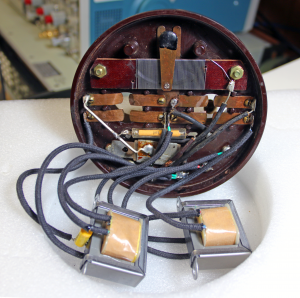
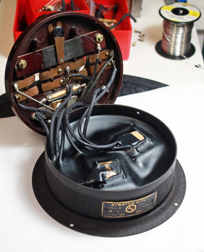
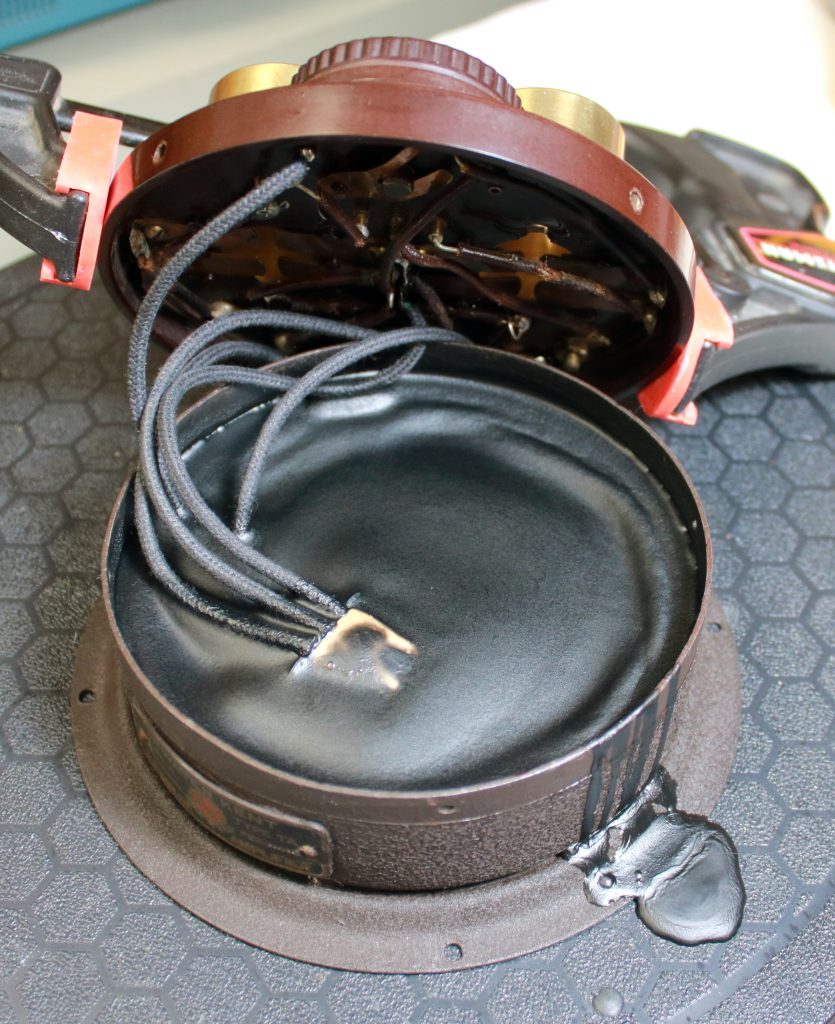
The DETECTOR-AMPLIFIER island required a lot of attention. Unfortunately, the original transformers were open, and (like all AK islands) embedded in tar. The entire tar puck was not hard to remove in one piece and was discarded. New substitute transformers were installed. These were type P-T156 from Antique Electronic Supply–they are electrically suitable for this purpose, but they look nothing like the originals. To improve the appearance, each wire was covered with old cloth sleeving. From top to bottom in the photo is the rheostat, the tube contacts, the grid leak resistor, a capacitor, and two transformers. The 10 ohm rheostat was working, fortunately, but it was corroding and had to be carefully removed, cleaned and treated. The 2M grid leak resistor was open. This was not hard to repair since it was in a glass tube. The 250pF cap was tested, deemed “close enough,” and left in place. A 2000pF capacitor was in the original circuit and embedded in the tar. Since the modern replacement looks modern, it was installed directly on the transformer wires so it would be hidden by the re-potting. All contacts were carefully cleaned and treated. Then the island was powered with an ARBE-III power supply and tested with an AM signal from a signal generator. After i was sure everything worked, I made up a batch of paraffin wax, dyed it opaque black, and re-potted the island to restore its original appearance. (Although it’s inside a can hidden from view, it’s likely the island will require periodic maintenance. The melting point of the wax i used is only 135F, so it won’t be hard to remove.)
The TWO STAGE AUDIO AMP had good resistors, but bad transformer, and the switch (for bypassing the last audio tube if it is not needed for listening) was broken. All was repaired, tested, and re-potted.
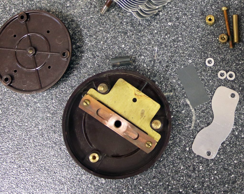
Fortunately, the 1st RF transformer (with the three taps to the antenna) was good. Note: the 600 ohm grid resistor to the 1st tube is mounted underneath the cup, and is a modern replacement. The original was severely corroded and open. It was a “dogbone” style mounted across the two mounting screws. On top, the three tap contacts were burnished and treated with DeOxIt. The coil measures 88, 20, and 4.4 mH across the common and three taps, viewed clockwise.
The 1st RF gain stage is a bakelite island, with the part number #4109-2 moulded inside. This did not work. I disassembled everything on it to sand the wiping contact (a bump that was so corroded I originally thought the nichrome wire was open), as well as the wiping contact to the filament. This is a spring copper piece inside the island. When everything was reassembled, the rheostat worked smoothly, measuring 10.8 ohms end to end.
The 2nd RF transformer (in its own island) seemed open, and didn’t fit the wiring. I ended up removing it and figured out it was mis-wired, so that was corrected. Note this has a modern 560 ohm resistor to replace the original dogbone that was an unprotected wirewound unit (that was open). No attempt was made to repair the dogbone resistor because it’s completely hidden, and would be a lot of effort. When finished, the primary (a hex loop glued inside the bakelite cup) measured 0.1 ohm DCR, and had ~7 turns. The secondary (the cotton covered cloth wound on the outside of the bakelite cup) measured 1.7 ohm DCR, and had ~64 turns. Inside was a part number #4583-10 molded into the bakelite.
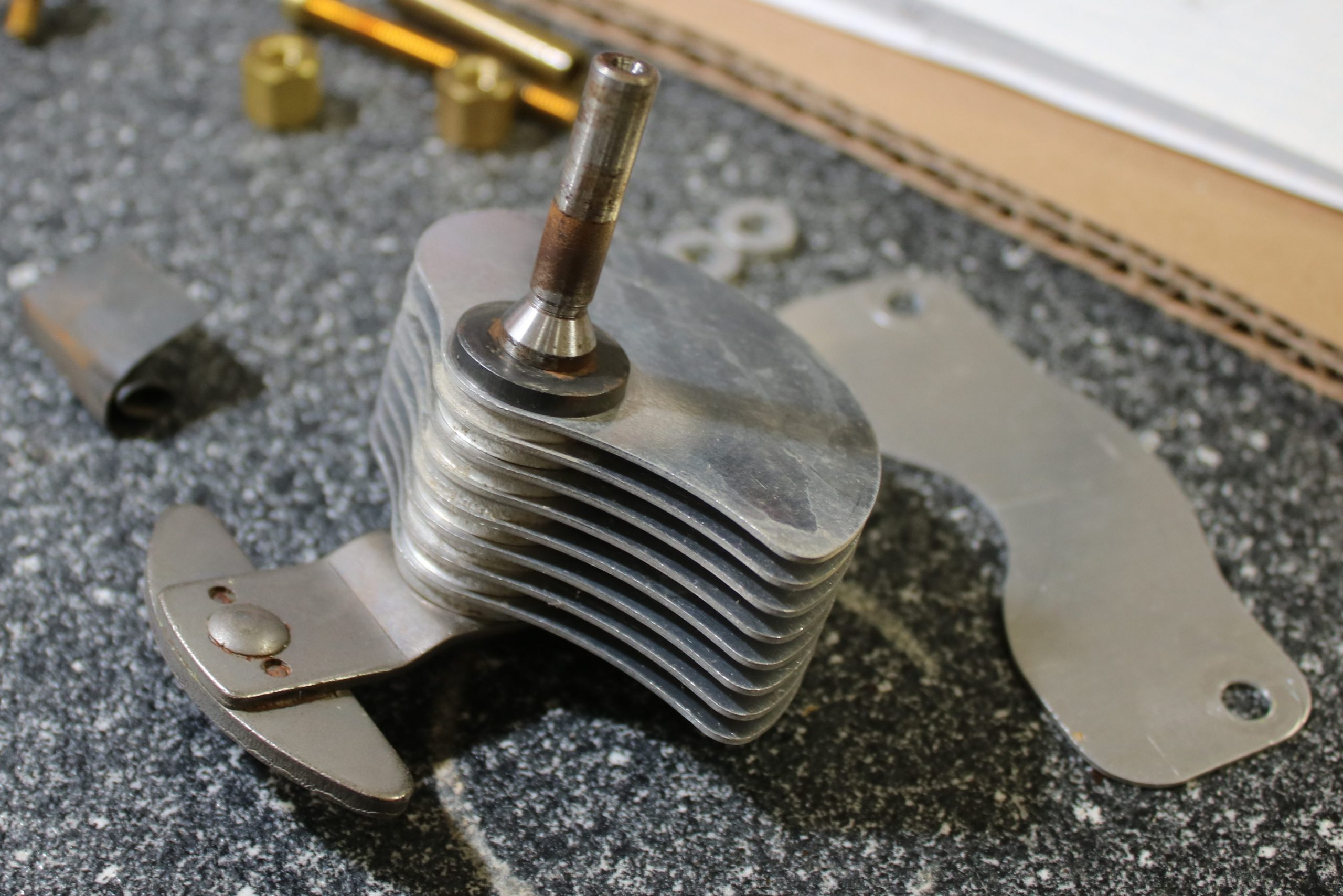
The 1st tuning condenser was intermittent (verified with a capacitance meter). This was removed and completely disassembled. The rotor was removed to get to the machined area that contacts the phosphor-bronze-copper wiper screwed into the bakelite. That pivot area was rusty and pitted. Both parts were wire-brushed, polished with 0000 steel wool, cleaned with acetone, then treated with DeOxIt. There is an electrical contact area on the copper back plate to which the wire is soldered. This was also polished and treated. I ended up taking out all the stator plates and treating each spacer, too, just to make sure every contact was pristine. It only took a few extra minutes. When it was all back together and the adjustment screw turned to re-center the vanes, the capacitor worked beautifully. I measured an adjustment range from 0 to 273pF. So I replaced the knob so that 0 pF matched 0 on the dial scale. I repeated this process on all three tuning capacitors.
Photo shows the pivot point that was polished and treated. (Notice the shape of the vanes; this makes the tuning more linear.) While this entire process took about 45 minutes, it is well worthwhile, as the radio’s sensitivity and ease of tuning depends on it. I would suggest always doing this step as a mandatory part of the restoration procedure.
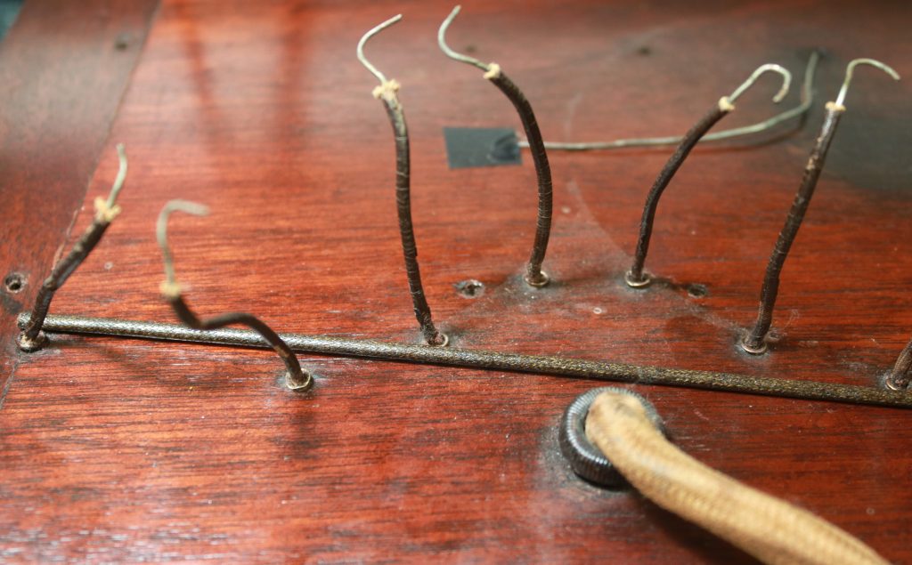
The next problem to tackle was the wiring. Some research was necessary to understand the original appearance of the wiring under the board. Consensus among collectors is that original AK wiring was 18-gauge tinned solid with cambric sleeves where needed. I confirmed this by measuring the wire at .0405” diameter. It’s stapled to the board as necessary to hold it in place. The staples had been installed on top of the solder joints, and were corroded. Also, there was a question of what the bypass capacitor originally looked like since the original was missing.
The official Atwater Kent Service Manual (circa 1928) was used for information on the appearance of the 4910. Our specimen had several differences. (1) The wiring layout is similar, except for the distribution of the battery power, much of which was covered in disintegrating cambric. (2) The illustration has some mysterious dark patches labled GR#1 and GR#2 (corresponding to the grid resistors). I saw another radio that had these: each one appears to be a scrap of black, canvas-like cloth, placed under the solder joints. I have no idea why or what this is for, but ours are missing. The actual grid resistors are hidden inside the components on the top. (3) The location of the two paper labels is different from ours. Our breadboard has the rusty tacks still in place with fragments of paper under their heads.
One poster on the Antique Radio Forums (Leigh Bassett, W3NLB) said the AK factory schematics are not correct. He drew correct ones dated 20 Dec 2013. In the process of restoring our radio, I found that his schematic was perfect and matched in every way, even the mis-labeled connections from the factory.
Many of the solder connections on this radio were cold. I re-soldered every connection.
There was the issue of crumbling or missing cambric. A lot of it (about 10 linear feet) is needed on this radio because of the way the power wiring is all laid out side by side. Because it cannot be purchased, this had to be made by hand. I followed a procedure described by Robert Lozier on the Antique Radio Forum, posted Nov 17, 2019. This worked perfectly using stuff I mostly already had in my shop (see photo below).
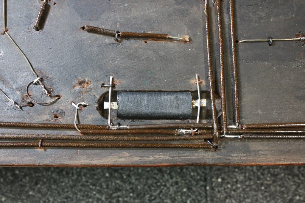
The .2uF bypass capacitor was replaced with a modern poly type. A 1920’s look-alike was made as follows:
- Solder two 0.1uF (400V) axial caps in parallel to a 1/8” wide, thin solder strap on each end
- Wrap the assembly in black gaffer’s tape (ShurTape P-628)
- Carefully fill each end with 3-min. epoxy; allow to settle and cure overnight
- Use painter’s tape to mask off the contacts and body; paint the ends with matte black spray paint
- Install two 18-ga wires laid across the routed out area in the board. The old staples indicate where these were laid, and soldered to the buss wires.
- Solder the above capacitor across the wires.
- The resulting appearance looks very similar to the original.
Now for the “smoke test”…
First connect the power supply sans tubes, and measure to ensure all the voltages are correct on the tube contacts, and rheostats are working.
Next, set the rheostats low, put in the tubes, connect loudspeaker (RCA type 100-A), and apply power. The ARBE-III A voltage was set to 5.0V to prevent harming the tubes, until I was convinced the set was operating properly. There was no smoke, and all voltages were normal. Tried raising the rheostats and tuning, and the radio worked properly. It was able to easily tune in local radio stations using my external antenna & ground (using TAP 2 because the AK instructions recommend this). At this point, knowing the 1st tuning dial was set correctly based on direct measurement of its capacitance (out of circuit), I adjusted the 2nd and 3rd tuning dials index to match the 1st. In this way, the 3 RF stages are “aligned” and the dial settings match the original AK Instruction Manual–at least in the middle of the band.
[Note: The 1st dial alignment does not hold up at the high end of the band, probably because of the use of the modern 560 ohm resistor in that 1st coupling RF transformer. I believe the original wire-wound 600W “dogbone” style resistor adds inductance to the coil, and the modern resistor lacks this, thus changing the Q. Not a problem from a practical perspective, because I used an AM signal generator and made a new dial calibration table.]
As was often recommended by the manufacturers of 1920’s radios, I swapped the tubes around (with the aid of a TV-7) to find the best arrangement. Tubes can be microphonic and will readily pick up the sound from the loudspeaker and howl as the filament voltages are turned up. The set of tubes that came with the radio from the museum varied significantly and swapping made big differences, but they were microphonic. So I kept the two best RCA tubes and put in a matched set of Sylvania tubes from my own stash. This worked well. Each of the tubes was marked underneath its base, and tested with a good tester. All of them measured 1250-1350 micromhos.
This is the measured current for each of the battery voltages, supplied by the ARBE-iii, with A set to 5.0V. Actual B+ voltages were 44 and 91V.
- the entire set required a total of 24mA @ 90V, with all 6 tubes ON, and all rheostats set at 2:00
- with the 6th tube switched off, the total dropped to 19mA @ 90V
- in addition to the above, the detector tube pulled 2.3mA @ 45V, at the 12:00 setting of the rheostat
- the entire set required 670-1175mA @ 5.0V for the filaments (6th tube off), depending on the setting of the rheostat
- the 6th tube added another 175mA filament current when switched on
Now convinced everything was okay, I increased the A voltage to 6.0V. Generally the best setting of the two rheostats is about the halfway point (12:00), which is then adjusted as needed for best audio. (It is interesting how the tone quality varies as the audio tube filament voltage is adjusted.) Also I found the last tube was not needed by my RCA 100-A loudspeaker, so it was always left turned off. This radio has plenty of gain. I would recommend keeping the A voltage to 5V, however, (1) to extend the life of the tubes, and (2) to ensure the plate current doesn’t exceed the 10mA rating of the transformers.
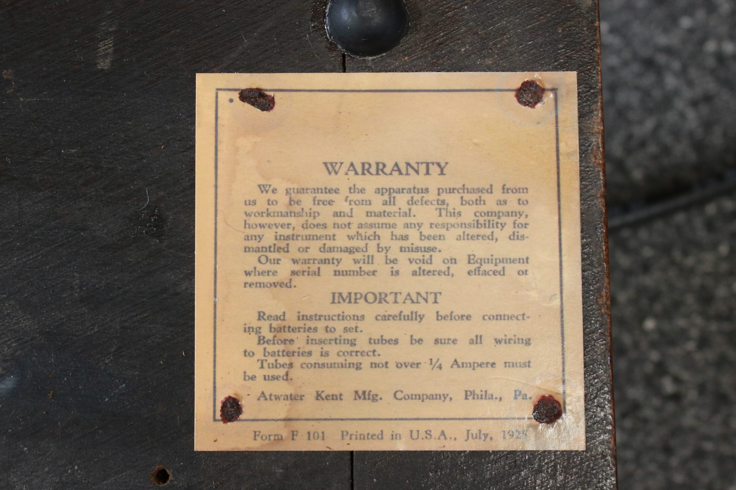
The original AK factory inspection label and warranty label were missing and could not be duplicated. However, some research on the web showed that Atwater Kent used the same or very similar labels on many of their sets. I was able to get a facsimile from Sonny Clutter (aka “Radiola Guy”) in Portland, OR, a specialist in making repro flatwork for many antique radios.
After scaling his artwork to match the outline of the existing tacks, I experimented with printing and aging. Printing on plain paper (or card stock) with an inkjet doesn’t look realistic, and the ink smudges easily. Fortunately I had some HP “Professional Business Paper” (type Q1987A) that worked well. The HP paper is glossy coated on both sides, and has a 48 lb. weight (thickness) that more approximates the thin cardboard of the originals. After printing, the edges were distressed with a kitchen whisk, then soaked briefly in coffee to make the backs and edges brown. (The artwork was designed to already simulate age and stains.)
The tacks that had held the original tags onto the board were severely corroded and could not be removed. So, after drying and flattening the new tags, I laid them on top of the existing tacks and pressed down to make in impression in the paper. Then holes were carefully made using drill bits and an xacto knife. The new tags were glued down using 3M type 77 spray contact adhesive. Finally, the tiny areas of frayed paper around the old tack heads were touched up with a brown sharpie. The end result is a reasonable copy of the originals and seem durable enough to survive the next 97 years.
Finally, to display the set in the museum, it needed a power supply. This set only requires 4 connections to two 45V “B” batteries and a single 6V “A” battery. The original plan was to use a small switching boost DC-DC converter for the B voltage, and a wall wart for the A. This plan was a huge fail: the switching noise made the radio buzz and scream bloody murder.
This led to an afternoon of testing in the lab of various wall warts and boost converters under load. But The “A” supply can simply be a 5V wall wart capable of supplying at least 1.5A. Fortunately, the world is awash in USB phone chargers that match this requirement. Because these are almost always switching power supplies, it’s necessary to check them under load (a 4-ohm, 10W resistor) with an AC-coupled ‘scope. I picked the quietest one out of my junk box and it worked well. The “B” supply should be an actual battery pack, because the set is very sensitive to switching noise (remember every plate is connected directly to the supply–switching noise is just another AM signal). I made up a pack of ten, fresh Duracell MN1604 (alkaline “9-volt”) batteries. The capacity of such a pack is about 550mAh at a load of 20mA according to Duracell. Therefore the radio should run for roughly 20 hours of intermittent use. A brief 2 or 3 minute demo is usually all a museum visitor wants to see, so this pack should last all season.
This radio tunes 550kHz to 1100kHz. This may seem odd, but remember that from 1923-1928, the AM band was in two segments. From 550-1040kHz were the “Class B” frequencies with fewer stations, higher powers, spaced in cities far apart to reduce interference. Some of these were later known as “clear channels.” From 1050-1350kHz were the “Class A” frequencies with far more stations, shorter spacing, and low power. Speculation is that Atwater Kent must have decided to not bother covering the Class A/local part of the band. By the end of 1928, the new AM band was completely restructured from 550-1500kHz.
This AK set is fun to use (I even tried DX’ing with it at night) and certainly cool to look at. Here are a couple of recordings i made off the air. (Note: these were made via direct electrical connection to the radio–not by a microphone–so you can hear how the radio actually sounds. We’re probably hearing better quality than the original buyer back in 1925!) This is using an outdoor longwire antenna, a ground rod, and my location is in Hendersonville, NC.
The radio was returned to the Museum for permanent display on 7 April, 2022. It plays well into a matching AK Type E loudspeaker, and connected to a random length of wire.