This project originated due to the need for a good, indoor antenna for AM radio listening. Trying to operate a radio in the house using its built-in antenna is frustrating due to all the electrical noise. This mainly emanates from the switching power supplies that are in practically everything now. Seriously, they have taken over the world. Counting all my LED light bulbs, wall warts, appliances, and all the other tech, there are at least 75 switchers in my house. Also, the AM band is so crowded that it’s helpful to add a pre-selection stage to reduce noise, and to turn a directional antenna to peak the desired station or null the others.
Mainly, it is a pain to put up an outdoor antenna that works well. If it’s high enough to reduce noise, or long enough to deliver good gain, it will be difficult or impossible to rotate. The wavelengths are just too long. For most, a broadcast band or shortwave antenna is little more than a large piece of random wire that picks up a lot of noise and signal from all directions. An earth ground greatly reduces noise, but the wire still is random.
It seemed like a good time to look at the indoor loop antenns that used to be commonly used in the golden days of radio, circa 1920’s. After the 30’s, these fell out of favor and were no longer offered, probably because of convenience and appearance. With radio being the primary source of electronic entertainment, the apparatus would be in the prime living space of a home. As tubes rapidly improved, thus improving sensitivity and selectivity, it was possible to integrate loops into the cabinets of the radios themselves. Often the manufacturers recommended connecting an earth ground, but even that mostly went away by 1950.
The antenna described here works extremely well with receivers that have an AM tuner built in. The 1970’s-1980’s era vintage hifi gear sounds great with this antenna. It also works very well with portable radios, mainly because the narrow bandwidth reduces overload. It is great with antique radios, and is good enough to fill the dial with stations, especially if a real, earth ground is connected. In fact, the loop is almost magic.
There is nothing magic about a transformer, which is what this is. The design process was straightforward. First, I decided on a 4-sided loop just to make the construction simpler. I started by assuming about 24” length for each side, that being a convenient size that’s not too big and not too small, and roughly comparable to what was commercially sold in the 1920’s. The voltage delivered by the loop is of course proportional to the area; the larger the loop the stronger the signal. But building something larger than 24” on the side would be awkward.
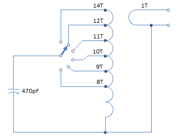
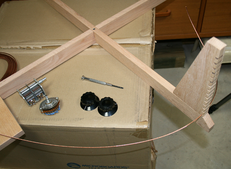
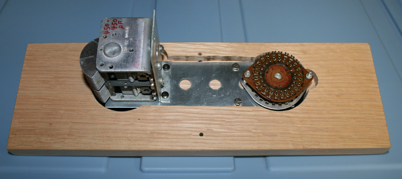
The loop was made using some stranded copper, 8AWG wire left over from an outdoor antenna project. This is commonly sold as “antenna wire” in ham shops. I had on hand a 470pF tuning cap scrounged from some old radio. I found the design equations for calculating the inductance and self-capacity of a loop, and made an Excel spreadsheet that implemented these equations. Then it was a matter of tweaking the number of turns, length of the sides, and turn spacing to calculate parameters that would allow the V.C. to resonate the antenna anywhere in the AM band.
My example worked out best at 14 turns, spaced 0.5” apart, using 8AWG wire (total length 112 feet), thus forming a loop inductance of 190uH. With the 470pF VC, this could be resonated anywhere from 511-1612kHz.
The circuit of the loop consists of a primary winding, that is resonated with a variable capacitor, and a secondary winding, that connects to the radio. I had a 6-pole rotary switch handy, so I connected it to allow switching of taps, so the loop could also be used on some of the shortwave bands.
The resonant frequency (in Hz) of the circuit that makes up the loop antenna is: 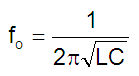
With L the loop inductance in H, and the loop capacitance in F. One simplified, practical formula for calculating the approximate loop inductance is attributed to Joseph J. Carr [ARRL Antenna Handbook, 20th Edition, pp. 5.4-5.6], and incorporating the work of F. W. Grover of the National Bureau of Standards. [This is also covered on a web blog located at http://earmark.net/gesr/loop/amloop4.htm, author believed to be Bruce Carter, and accessed on 3 April 2016. His equation graphic is copied here.]
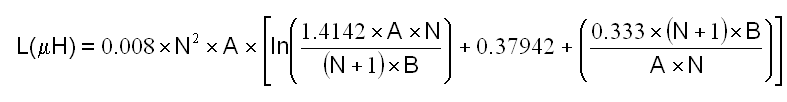
- A is the length of the side, in cm
- B is the overall length (thickness) of the loop, in cm
- N is the number of turns
This equation is a close enough approximation under these conditions:
- Square loop (other shapes change the value)
- Loop diameter < l/10 wavelength
- Loop diameter >> loop thickness
- Frequency of operation < 100MHz
Note the equation doesn’t include wire diameter because it doesn’t significantly affect the inductance. It does affect resistance, and hence Q. The larger the diameter, the lower the resistance, i.e. stronger signal level and higher Q. But there’s little to be gained by using larger conductors than the inexpensive, common 8-gauge antenna (or ground) wire.
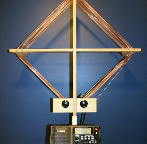
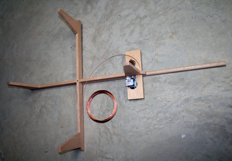
For best appearance and performance, the wire should be stretched tight, but the supporting structure must be non-conductive. So a strong hardwood was used. I had some seasoned white oak on hand, so I used that. The pictures show what I improvised. One photo shows how I cut the grooves that support and hold the wire turns in place.
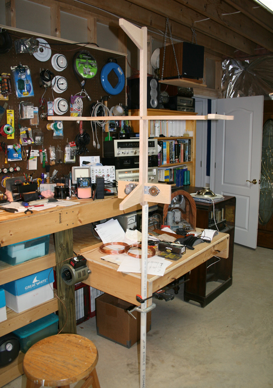
The 1.5” dowel rod makes it handy to stand the antenna up on a base (for example, a heavy cast iron patio umbrella base) and allows for turning the loop. The finished product agreed reasonably well with the equation. The predicted tuning range was 511-1612kHz. The actual tuning range was 522-1689kHz. When connected to an old tube radio, it’s possible to listen to many stations up and down the dial without having to connect an outdoor antenna.
1 Comment
Steve
August 8, 2021 - 10:45 pmVery nice looking antenna. Thanks for sharing.😊