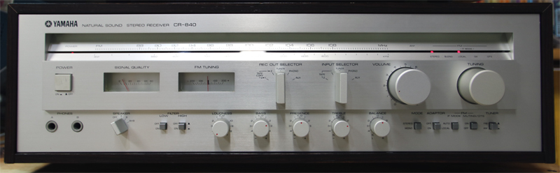
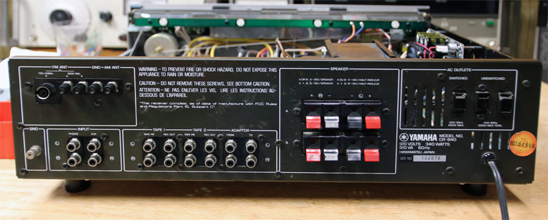
The Yamaha CR-840 came out in 1979 or so, and priced at $500. It was a fairly good audio component at that time. I found one at a yard sale for $10, and could tell immediately it was worth purchasing if only to get parts and a nice power transformer. I ended up cleaning it up and using it with a pair of Design Acoustics PS-10 speakers from the same era. The sound is nice, and the CR-840 allows me to connect all my vintage analog gear. The so-called “integrated receivers” of that era excel at providing a lot of handy interconnections: turntable stages, two tape decks, ability to “dub” from one to the other, built in tuner, etc. The tone controls are typically very useful; this one in particular has a very cool “Loudness” control. On the other hand, I’ve noticed that many of the receivers of this era were not so great in two areas: noise and power amp. Noise was caused by a lot of hand-wiring running all over the chassis, and the power supply which only gets worse with age. The power amps don’t suit my taste. I grew up with 1970’s-1980’s audio gear, but when i listen to some of this equipment today it doesn’t have the richness and smoothness of very good tube amps, and lack the clean, accurate sound of modern audiophile solid state amps. However, the “spec wars” of the 70’s were fun and some great gear was produced. The best of the era I’d say was known for:
- Heavy front panels, intuitive controls and meters with tactile, nice feeling knobs and switchgear
- Tuners! FM radio was wonderful in the 70’s and worth listening to
- Widespread use of turntables, some of which were well-made, and produced very good sound if used properly
There are some quality touches in the CR-840. The inputs and outputs are switched by a wiping slide switch near the back panel, controlled by a long shaft to the front panel. There is a continuous loudness control that works quite well. The FM stage has 4 gangs and 5 ceramic filters. They seemed to put a significant effort in the FM stage and the specs look pretty good even today.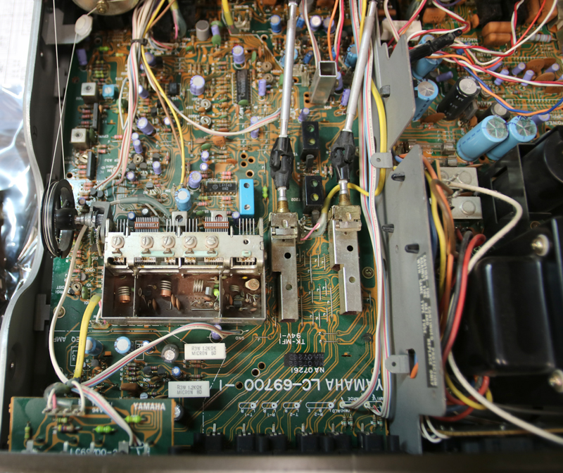
- 60 W rms into 8 ohms from 20-20,000Hz at <0.02% THD
- Tone control turnovers: 350Hz, 3000Hz, and 3.5kHz
- Phono S/N ratio: 94dB (IHF-A); Aux, tape 1, and tape 2: 100dB
- Damping factor: 40 into 8 ohms (at 1kHz)
- FM usable sensitivity: 3dBf (1.6uV @ 300 ohms)
- FM 50dB quieting sensitivity: 3dBf mono; 37.3dBf stereo
- Alternate channel selectivity: 48dB local; 82dB DX mode
- S/N at 65dBf: 80dB stereo (IHF); 84dB mono
- Spurious response ratio: 100dB
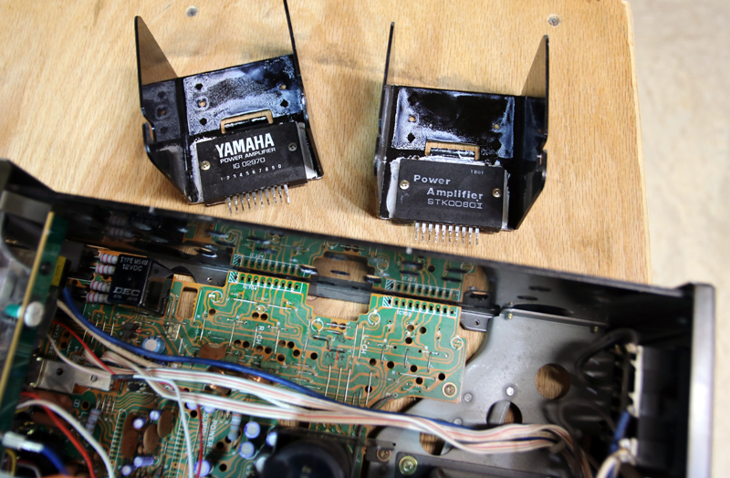
Anyway, this receiver is my “daily driver” and not long after getting it one of the output transistor modules died (part number IG-02970). The CR-840 sat in my shop for a couple of years, because I couldn’t replace it. Then I bought one of the STK 0060-II modules from an eBay vendor, after reading someone’s blog saying it was a pin for pin replacement. This worked well for about a year, then the entire power amp quit. (Not the relay or the power supply; possibly the driver modules.)
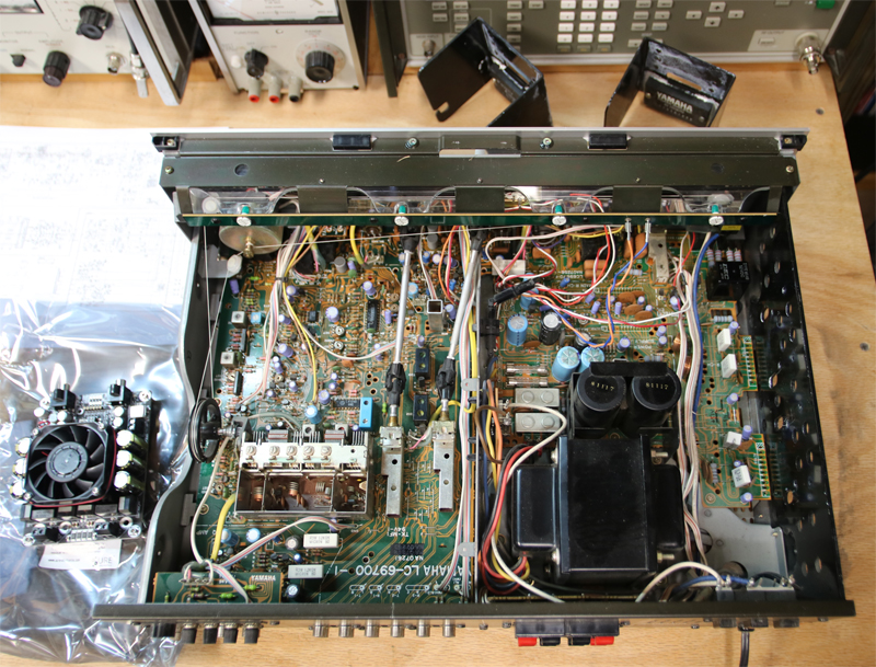
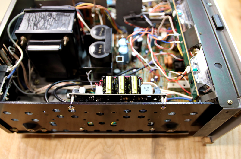
Finally, I hit on the bright idea of removing the power amp completely and replacing it with a modern Class D amp module. Why not: the DC power is available (53VDC bipolar from a large 31.8VAC CT transformer) and after removing the modules and heat sinks, there was ample room inside the case. This would give me the best of both worlds: all the control capability and the 70’s sound and tactile switchgear, with a modern amp with clean sound, low noise, and high efficiency.
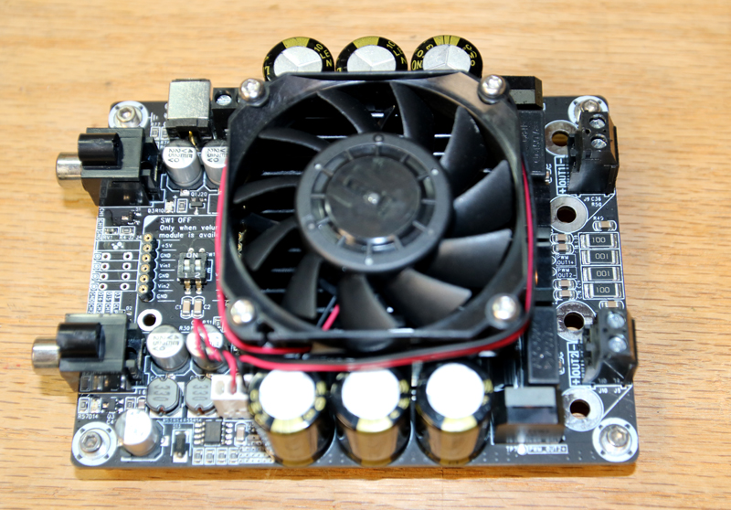
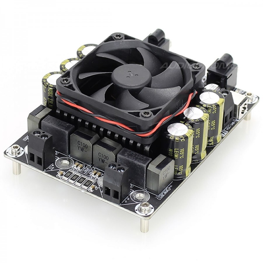
I originally planned to buy Hypex modules. But these were more expensive than I was willing to put into this project, and honestly a bit overkill since the S/N and other audio performance of the CR-840 would fall well short of the Hypex amps. So I went back to Sure Electronics (Parts Express) and shopped there. There were many choices, but just a few that would work on the available DC power. I settled on the AA-AB32313, because it had some of the best specs, and seemed to have a bit of credibility in the DIY audio community. And I had fairly good experience with a Sure module before. Basic specs are 2x400W at 3W, switching frequency 650kHz (the higher the better); 0.005% THD (10W out); 204uV noise (by comparison, the Hypex modules are 35uV); 97dB SNR. While most of these specs are claimed without telling us the test conditions, they do look better than the other Sure Electronics products. Worth a try.
This was a surprisingly easy procedure. First, I removed the output power amp modules and their heat sinks. Then remove the caps and power resistors in the power amp stage. This created an area that the Sure Electronics module could easily fit into. Notice the module has four standoffs. It was a simple matter to measure and mark off the pattern in the side wall of the CR-840 (where the original heat sinks were), drill the 4 holes, and bolt it in place.
Also, I removed the two original Yamaha preamp modules (IC701 and IC702). One is the left channel; the other is the right. Pin 1 is the line level input, Pin 2 is ground. Pin 1 is noted on the PCB with a hash design. This is the line level audio signal after all the tone controls and switchgear, so it’s a very convenient place to connect to the new module. Solder a shielded cable between these points on the PCB over to the RCA connector pins on the new module.
To make connection to the existing speaker terminals, note there is a 3-conductor wire going to the CR-840 PCB. Unsolder these (Left and Right speaker outputs) and then they can be attached to the Sure Electronics output screw terminals. Finally, locate a convenient place to connect a wire to the +53V power bus, and run that (and a ground/chassis wire) to the connector block on the module. That’s it!
The only feature lost in this arrangement is the use of the headphone jack. In the CR-840 this was driven off the power amp module. The proper way to restore this is to install a dedicated power amp and wire it to the jacks. I never use this receiver for headphone listening, so I didn’t bother.
Now, to test the amp. I was interested in basic audio measurements made both through just the Sure Electronics module by itself, and the entire system including the CR-840. Since the new module has RCA jacks pre-installed, I simply switched the front panel switch labeled ADAPTOR to ON, which completely cuts off the line input to the amp. Then I could put the test signal directly into the rear panel. Nice.
After re-assembling the case, i ran a “smoke test.” No problems. The system played very well with my PS-10 speakers, in fact it sounded very good, and just as expected. What is odd is how good FM stations sound through this setup (with the wide IF filter switched in); our local WBIG 100.3 (classic rock) was exceptional.
Naturally, i had to test the modernized receiver to see how it performed. Tests were done with the receiver connected to a resistive dummy load, the test signal into the TAPE 2 input, and all tone controls set to flat, and both filters off.
Quick gain check:
- 500mVrms and volume set to 5 produces 1.35Vrms into 8 ohms. This is 228mW power, and 22.6dB gain
- 500mVrms and volume set to max produces 12.06Vrms into 8 ohms. This is 18.2W power, and 41.6dB gain.
- 1000mVrms and volume set to max produces 36.0Vrms into 8 ohms. This is 162W power, and 51dB gain.
These are well matched to the kinds of signals that would be presented to the amp…
Clipping level:
Set the volume control to produce exactly 20dB gain (this was about 4.5 position on the dial; 500mV input produces 5.0V output across 8 ohms). Under these conditions, the amp is linear in amplitude response from <1mV up to about 1.8Vrms.
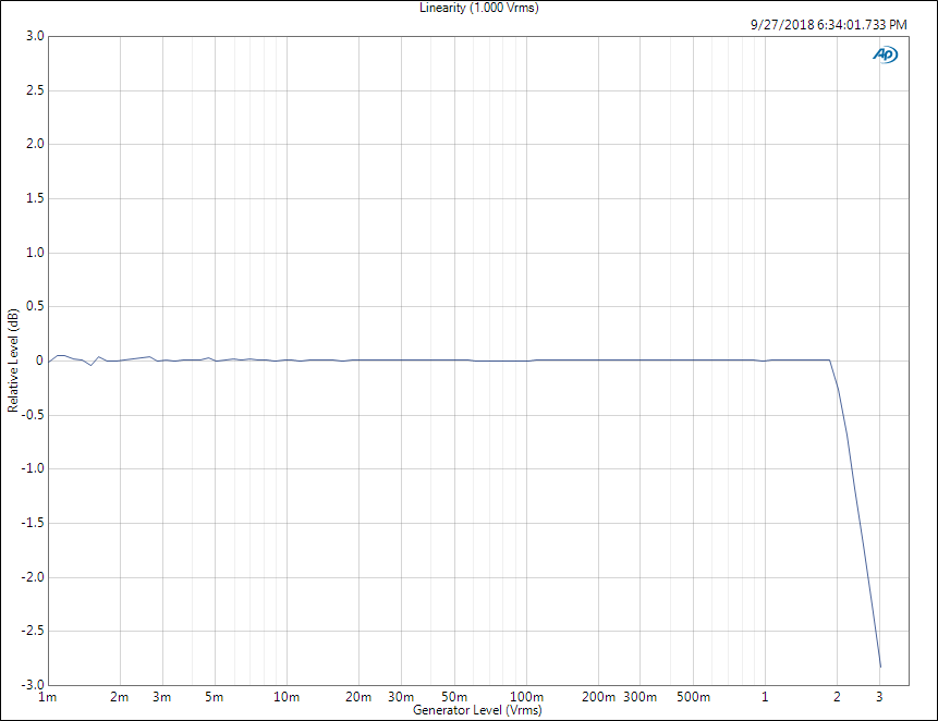
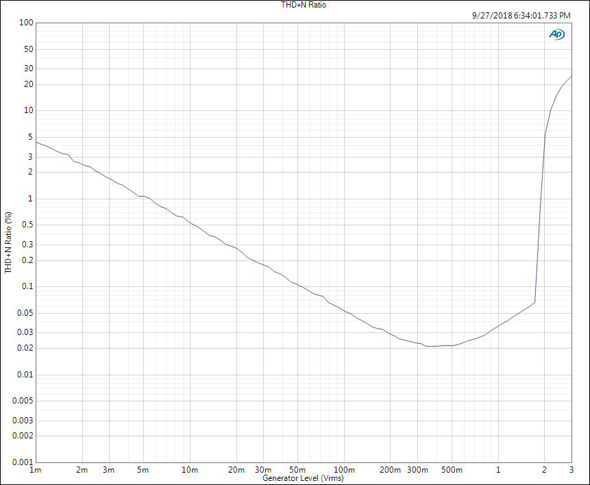
The THD+N (A-weighted) versus input amplitude is shown in this plot. It gets down to about 0.02% which is not bad at all.
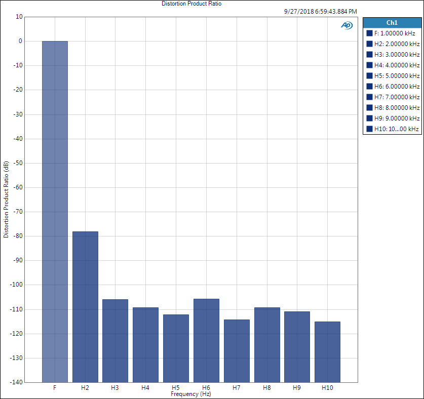
Distortion characteristic was tested with the volume set at about 5. With a 500mVrms input, an 8 ohm load, the measured output was 7.782Vrms (gain 23.8dB). The distortion products are shown here:
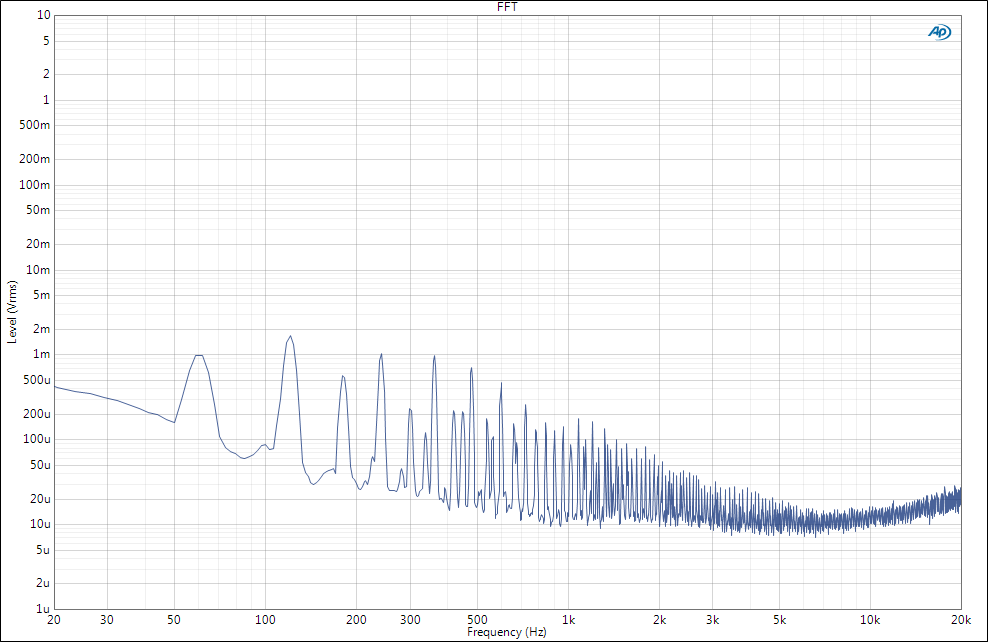
And the FFT view of this (64k points, AP-Equiripple window, 10 averages) is:
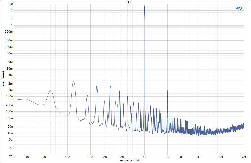
This raises an interesting concern, and explains why the best SNR i could achieve was about 70dB. With the test signal off, notice the power supply noise:
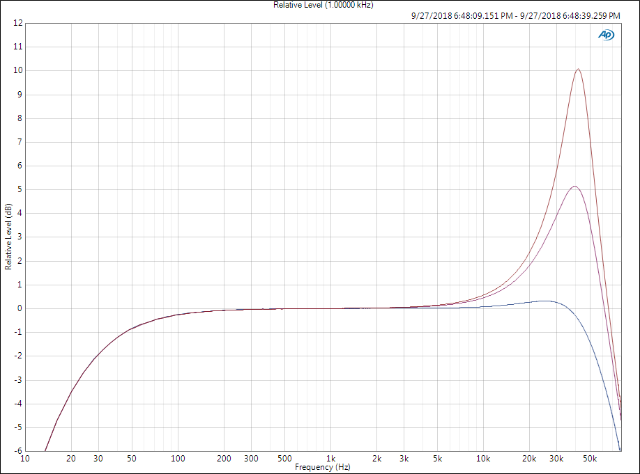
Frequency response was measured with 4, 8, and 16 ohm loads. This plot goes out to 80kHz because i was concerned about switching frequency noise on the high end. The bottom (blue) curve is 4 ohms; the middle (violet) one is 8 ohms, and the top (red) one is 16 ohms.
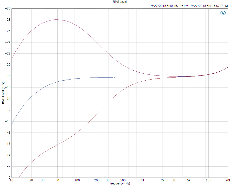
The next plot shows the effect of the BASS control at minimum, flat, and maximum settings:
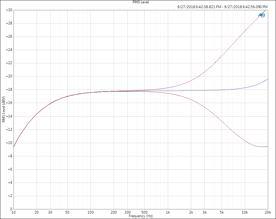
The next plot shows the action of the TREBLE control at min, flat, and max positions:
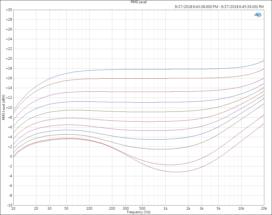
This plot shows the action of the LOUDNESS control, with the volume set at 5. The top (blue) curve is with the control set to FLAT. Each curve represents one detent on the control, with the bottom (violet) curve at the maximum setting of 10.
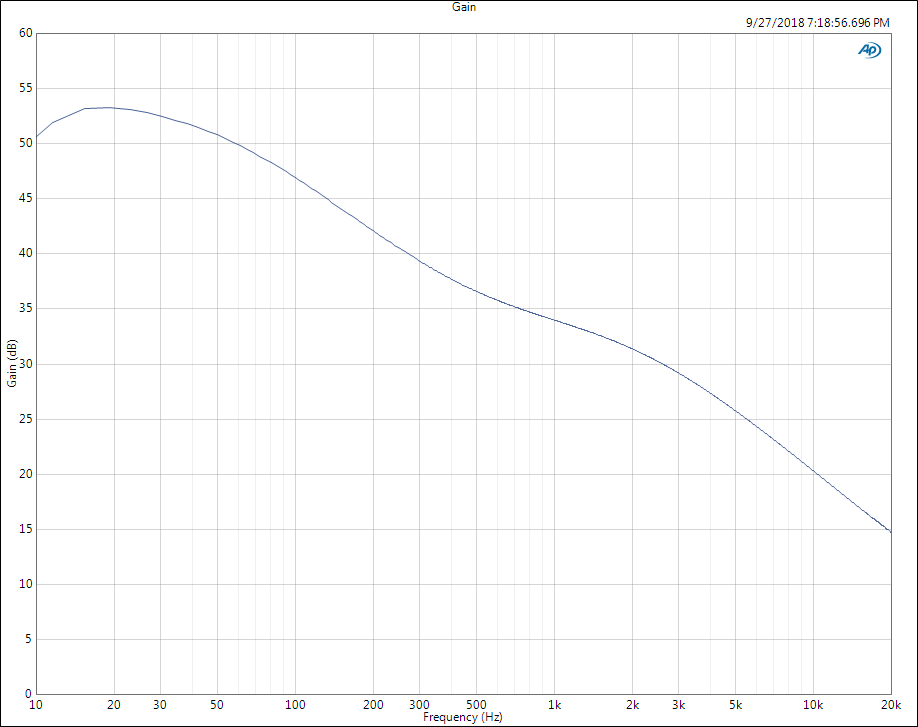
And this is the RIAA phono response, using a 10mVrms input level, and measured at the TAPE1 output. The SNR was about 70dB, nowhere near the advertised 100dB, and clearly suffering from the same power supply noise.
Other tests were run, but this covers the highlights. Even though the power supply in the CR-840 is degrading S/N by 20dB or so, requiring some new caps and other troubleshooting to repair, the system sounds quite good, in fact surprisingly so.
I would highly recommend doing this kind of repair to vintage amps/receivers that are good enough to be worth repairing and keeping. The cost of this Sure Electronics module isn’t much more than finding a replaement for the OEM power amp and preamp/driver modules, and has better performance.
UPDATE 8/27/2022
This receiver still works just fine. It was in daily use for over a year after completing this project, and has only been used occasionally since (circa 2022). Have had no problems.
5 Comments
Ryan
January 6, 2022 - 3:45 pmHas this modification continued to work well over the years?
I picked up a cr-840 off Facebook and it worked great for a sec but the output is incredible erratic now. Right side will be quiet for a bit…. Then come back. Then I’ll turn the volume up and the left side will fall off.
Nick
February 20, 2022 - 12:32 pmVery cool project!
Curious how you connected the output from the pre-amp to the board? Did you install terminals, or solder to the board?
Also, why didn’t you tap in the speakers prior to the speaker selector? Wouldn’t this allow for the function of the selector (maybe the headphones too?)?
Tim
August 27, 2022 - 7:32 pmI found the preamp output points on the board and wired small jumpers over to the module. As for the speakers, you’re right it would have been better to do it that way. But it was difficult to get into the jumble of wires under the chassis without a lot of dismantling, and i wanted to finish the project. I decided to leave well enough alone and give up the use of the headphone jack.
Evan
January 11, 2023 - 1:29 amWith the preamp modules removed would this affect the sound quality of a connected turntable?
Tim
January 12, 2023 - 7:46 pmHi. Removing the audio preamp and power amp as i described will not affect the phono stage. The turntable plugs into a separate preamp stage that is necessary to make vinyl sound correct. The output of the phono preamp stage then goes to the switch that selects all the other audio sources, i.e. tuner, tape, cd, etc.