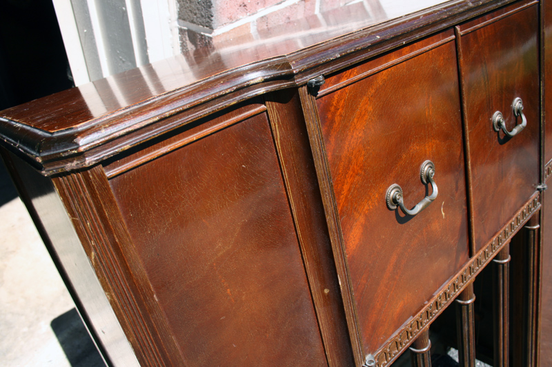
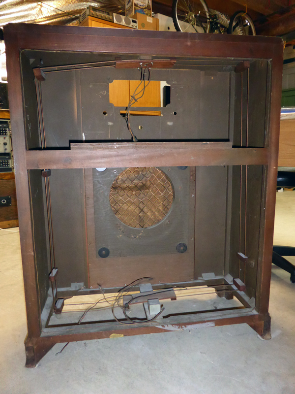
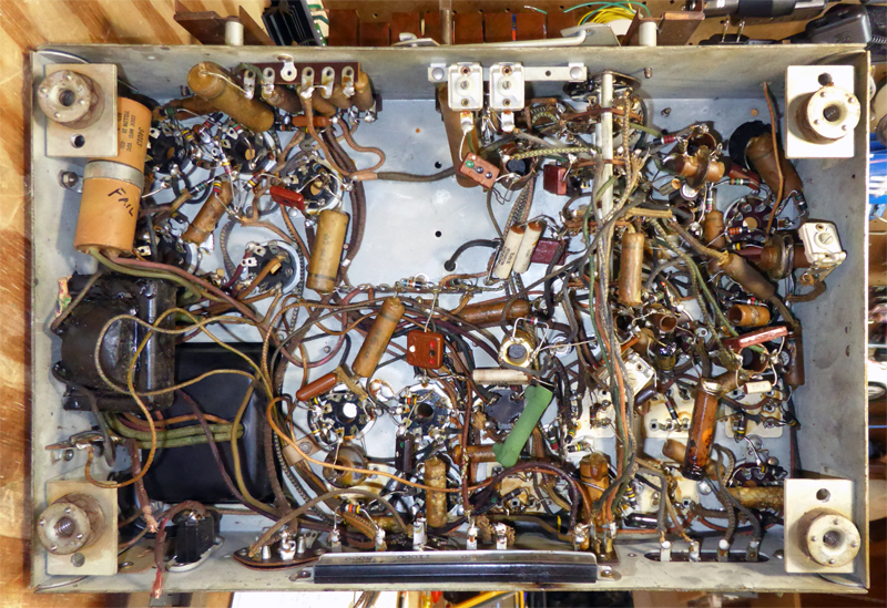
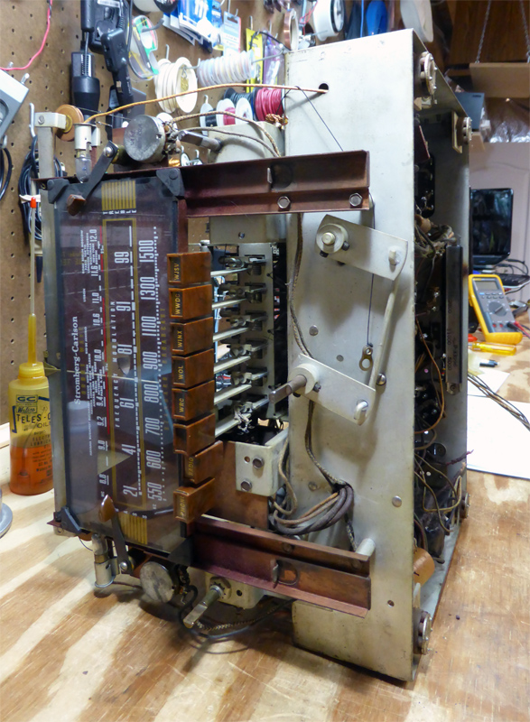
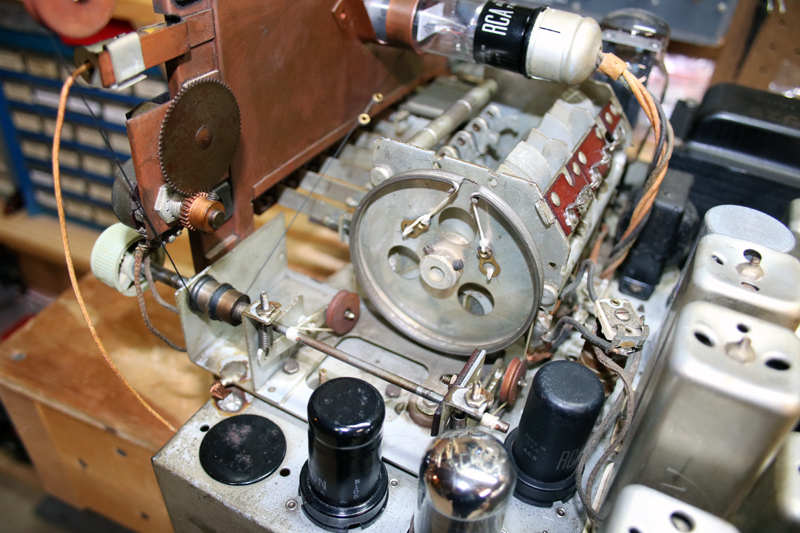
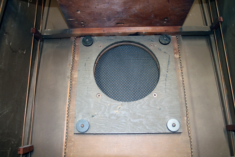
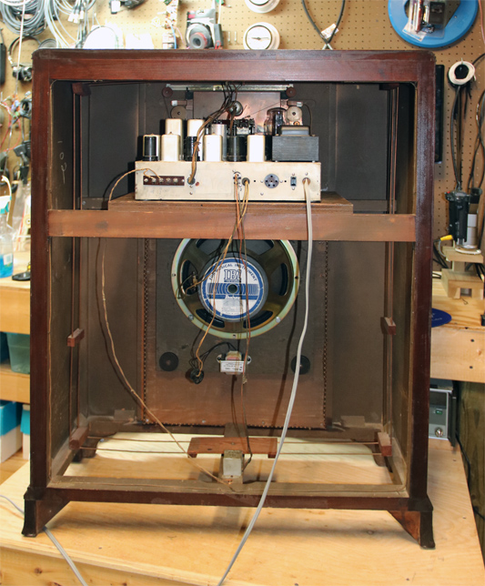
This radio was offered to me by a friend who was remodeling a house and wanted it out of the way. Normally I don’t take console radios, but this one seemed unusual and of higher quality than most, so I took it home. It was in fair-poor condition. The cabinet was scratched up and not cared for, but no veneer or parts were missing. One leg was falling off but that was an easy fix. All knobs were present. The grille cloth was ruined. Well, actually, the speaker was totally gone. It appears to have cracked apart…perhaps a pot metal basket, for only ¼ of the frame was left hanging on the baffle. The cast epoxy escutcheons around the dial and pushbuttons were very warped. The chassis had the usual heavy grime, but it was not good to see that some components showed signs of heat damage, burnt insulation. Some of the caps had leaked. Tuning mechanism was unravelled, but the cord was still there. All the tubes were present.
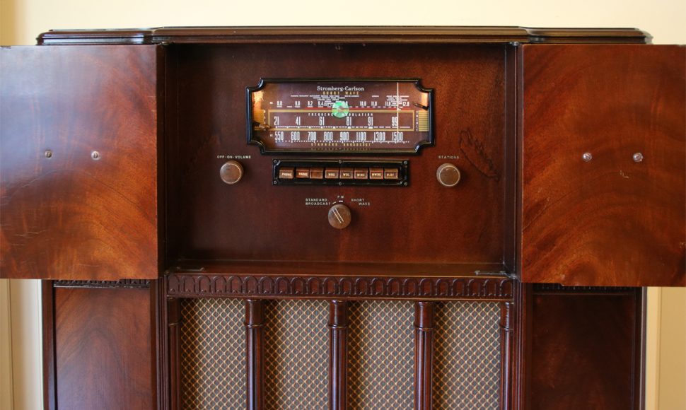
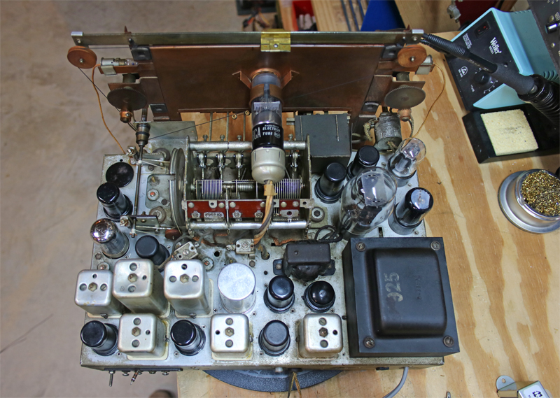
On the positive side, it was a higher-end radio: the wood was mostly mahogany (though the sides were very thin plywood), it carried a 12” speaker on a suspended baffle, had a 6L6 push-pull output, 14 tubes, separate bass/treble controls, a sensitivity switch, and a 6E5 magic eye tube. There is a set of push-buttons for preset stations. But most interesting is the “FM” band, ranging from 28-99MHz!
This radio sat in my basement for a long time before I decided to tackle it. Even then, I kept thinking, is this really worthwhile? But the strange band plan and high-end features kept me motivated. A few other oddball things were noted: a “bass resonator” coil mounted on a cross-brace in the bottom of the cabinet and wired into the chassis. A tuning mechanism with two cords and adjustable tension springs. And the cabinet hid two antennas: a simple wire dipole stapled up the sides and top for FM I guess, and a movable 2-turn, square loop hanging from the top.
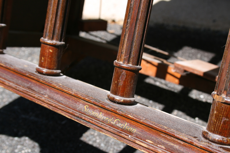
It took some time to locate information on the web. There was no information on the chassis or in the cabinet, so I used radiomuseum.org to search for tube compliment, and narrowed it down to just a few models. Then I eventually found photos of the Stromberg-Carlson 925 family consoles, though none had the same bandplan as mine. (Every photo I saw as for the 50-54MHz FM band, not 28-99MHz.) Eventually I figured out this is a 925-L, made in 1941. Original price unknown. Thank goodness that some great person put the schematic and alignment guide on the web! That seems to have shown up in the fall of 2013. The chassis was marked “Chassis PC No. 33264.” S-C used this chassis in several models: 925-H was a tabletop cabinet, 925-L a console, 925-PFB a console with a record changer, and adding M meant mahogany cabinet. Thus, 925-LM.
Thankfully, the output transformer and the power transformer were both good. The power xfmr is a large, heavy item on the chassis. The output xfmr is a dinky thing mounted underneath, and shimmed with a piece of paper. It measured 339W on the primary and 0.4W across secondary. Good! That would have been difficult to replace. So having eliminated problems with the two hardest items to replace, I examined the capacitors. A couple of the caps were leaking some kind of oily, sticky substance—probably carcinogenic.
I had to spend some money on this project. First, the can cap was the most expensive item. The original was a 40/30/15/15uF (450/450/350/300V) multi-section that was completely shot and sizzled when powered up, so I purchased a 40/40/20/20uF unit from AES for $37.95. Expensive but it was a perfect fit replacement. Underneath was a “firecracker” rated 15/8/20uF (400/250/25V) that required separate replacements: 22uF/450V, 22uF/50V, and 10uF/450. There were even some dual 0.01’s in a single tube. Fortunately all caps were marked with their values, not just the 5-digit S-C part number. There were over 30 smaller tubular caps in this chassis! I ran out of .01uF units, which seemed to be all over the place. I don’t think I’ve ever worked on a chassis with so many damn capacitors. But over the course of a month I finally got them all switched out. Yikes! Total cap bill $66.30.
One area of concern and puzzlement is a ballast resistor. The schematic doesn’t give values, just a S-C part number. I eventually puzzled it out, and it at least wasn’t open or shorted so I assumed it was OK.
It took me a while to figure out that the filter choke was actually not in the chassis at all, but had been mounted out on the speaker. The original speaker was an electro-dynamic type, with a field coil that doubled as a filter choke. This item was lost, so I had to substitute a small unit I had in a box that would let me fire up the radio for a few minutes at a time before it got too hot. It’s noted on the schematic as 575 ohm. The choke I had was 297 ohm DC resistance, and I measured 142mA current through this (about 6 Watts, regardless of volume). I was unable to find a choke with such a high resistance, so decided to purchase a Hammond 158Q (a common part used in a lot of amps) rated 105 ohm and 150mA. This in series with a 470ohm/10W resistor worked perfectly. Another $21.92. I purchased some S-C decals and grille cloth, total $76.12 for the order from Radio Daze. This is getting expensive.
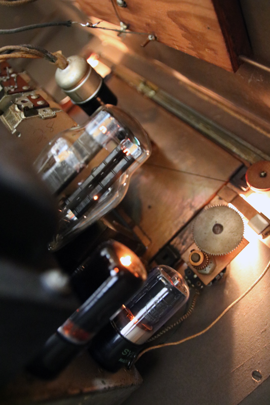
All the tubes were tested and were good. I did several other typical repairs, such as burnishing a lot of switch contacts, getting the 6E5 to indicate, etc. After bringing the chassis voltage up slowly on a variac, everything powered up and it worked. Only a little bit of alignment was needed to peak everything up.
I spent a couple of hours figuring out how to wind the two separate dial cords that operated the tuner and the dial indicator. There was no documentation on how to do this, so there was a lot of trial and error.
With the electrical restoration complete, I turned attention to the cabinet…
Refinishing the Cabinet
One problem to solve was the dial and button escutcheons. These were badly warped. In fact, I almost didn’t do the resto project because without these, the case would look bad. Fortunately my wife came through with a solution to the problem. Boil them! The idea is to put them in boiling water, get them soft, then lay them onto a cold flat surface (our kitchen countertops are granite and perfect for this), and then use carpenter’s squares to bend and tweak the escutcheons back into straight and plumb shapes. It worked great. After cooling for a day or two, they were perfect. However the finish had turned a chalky gray. This was easily removed with alcohol and a soft rag. Then I spray painted them with two coats of brown toner. After this dried, they looked brand new.
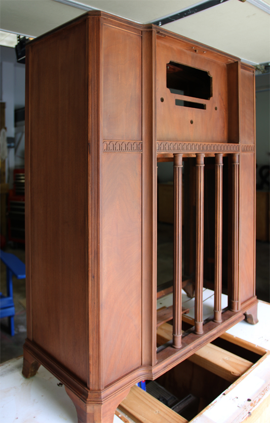
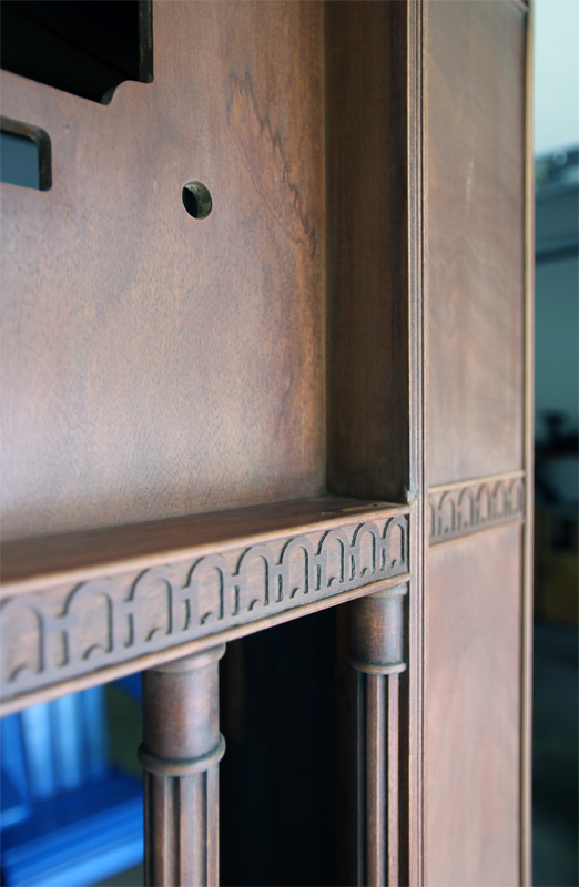
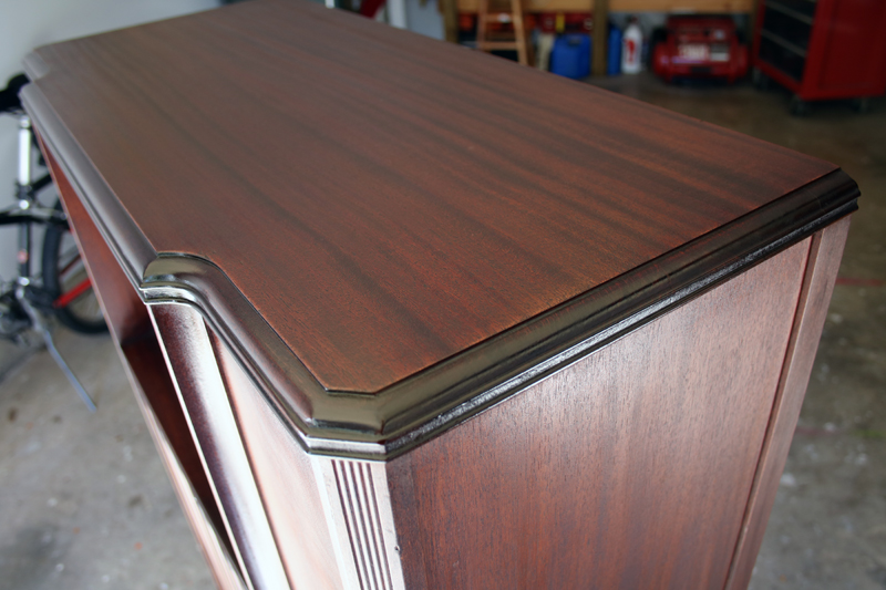
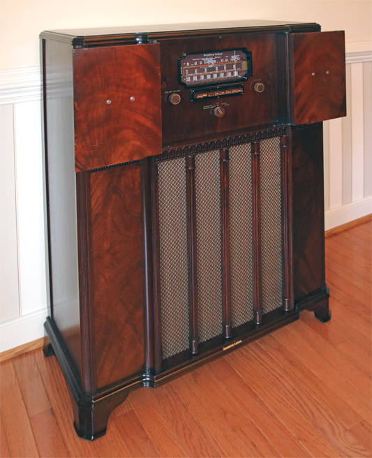
Now I could focus on the cabinet. It’s nicer than most because it was the more expensive mahogany version. My sample had a ruined finish, but almost no physical damage (gouges, missing parts, etc.) to deal with. I set aside the two doors because the insides of these were perfect, so I could use that to match the color and gloss of the finish. In the end, I matched so well that I didn’t even have to refinish the doors.
I followed my usual procedure for refinishing radios. Before starting, I took a lot of photos in diffuse sunlight, wrote down notes such as where the toner was applied plus its color and opaqueness, and used graph paper to trace where the legends and logo were located.
First use a gel stripper, applied with a cheap paintbrush, and removed with a putty knife. An old toothbrush, fairly stiff nylon parts cleaning brush, and fine steel wool were used on carvings and in corners. It took 3 rounds to completely remove all the finish and blotches. This was a pain, but well worth the effort. Next the cabinet was wiped down with a cloth soaked in mineral spirits, until no color came off in the cloth.
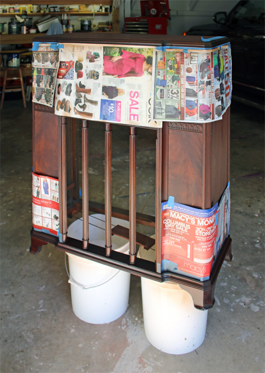
Next is application of a water-based stain. After allowing a couple of days to dry and evaporate, I applied the toner. The Mohawk “perfect tone” product in the spray can works great for this. This involves taping off the panel areas and using good judgment. There are other little details that I detail in a separate article. Then I applied the water decals. Next was a nice finish of glossy lacquer, built up in 4 coats. Finally I let it sit for two weeks in our cool, dry basement to thoroughly dry and evaporate.
Other things I needed to do was re-set the floating baffle, repair the square loop antenna so it hung within the cabinet correctly, and replace the speaker. For the speaker, I harvested one from an old Ibanez guitar amp I had purchased at a flea market. The 12” speaker was the perfect size, it worked electrically with the radio, and those things were intended to be in open-back cabinets so it was a good match.
Audio Performance
Since I am a total audio geek, of course I had to measure the performance of the radio. It has a 6L6 push-pull output stage, 6SC7 inverter/driver, and 6SQ7 audio preamp. The original Rider’s service manual said this radio has a power output of “10 watts 10% distortion, 16 watts maximum.” (The voice coil impedance was 3.5W.)
To measure power output, I connected an 8W dummy load resistor, connected the bass resonator, and set the bass and treble controls to their center positions (flat). A good 1kHz sine test source at 430mVrms was connected to the aux input on the radio (convenient), and an oscilloscope was used to measure the voltage across the dummy load. Distortion was measured with an HP8903B analyzer, for different settings of the radio’s volume control.
| Voltage across dummy load | Power into 8 ohms | THD+N (30kHz LPF) |
| 1.02 Vrms | 125 mW | 1.65 % |
| 2.08 Vrms | 540 mW | 0.95 % |
| 2.50 Vrms | 781 mW | 0.94 % |
| 3.01 Vrms | 1.13 W | 1.01 % |
| 4.07 Vrms | 2.1 W | 1.46 % |
| 8.75 Vrms | 9.6 W | 9.95 % |
For the rest off the tests, the volume control was left at the 2.50V setting since that was the lowest THD. Also, I used a Raspberry Pi and a HiFi Berry DAC+ as a test generator. (More on this in a separate article.) I did not have access at the time to an audio analyzer, so this was my improvised method to check, at least crudely, the radio’s performance.
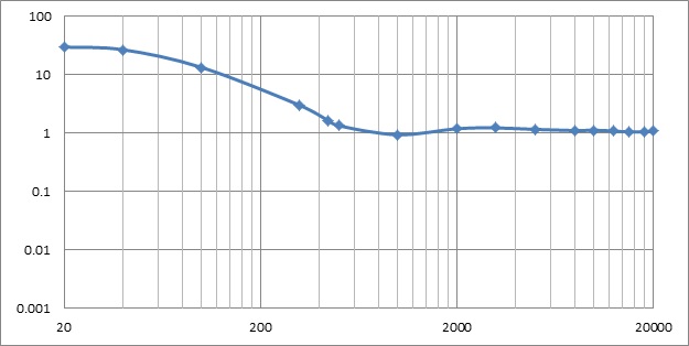
The first graph is a plot of THD (30kHz LPF) of the radio versus frequency, with the bass resonator connected, and tone controls set to flat.
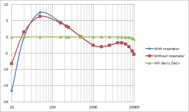
Following is a plot of frequency response, with and without the “bass resonator” and the output of the HiFi Berry DAC+ used to drive the radio.
The next plot shows the action of the tone controls. For each of the four plots, the indicated control was set to its maximum or minimum position, while the other control was set to flat. Keep in mind the Baxandall tone control had not yet been invented, so the action of these controls is not what we are used to seeing today.
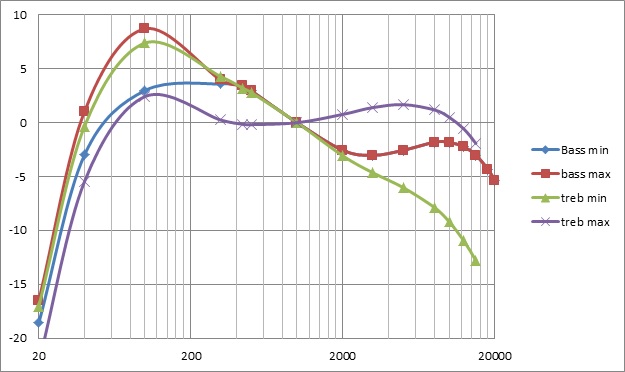
Subjectively, the radio sounds like many of this era: rich and “warm” …sorry for the cliches but this means voice is very pleasant to listen to and music has a deep low end. Since I don’t have the original speaker I can’t gauge how the radio originally sounded. But this radio never fails to receive compliments on the sound. I find it sounds best with the bass control set flat and the treble set nearly to its max (i.e. the purple curve above).
Radio Trivia
What’s most interesting about this version of the 925-L is the band plan. For one, I really like the limited coverage on SW to just 8.8-12.0MHz. This “bandspread” allows for realistic tuning in of foreign stations in the most popular part of the bands. But I did some reading and discovered that 1941 was an interesting time in broadcasting, and this radio was evidently designed to cover all the possibilities!
The radio came with the following push-button labels: WRC, WOL, WINX, WWDC, and WJSV. So what frequencies are these Washington, DC stations? Depends on when the service-man put the labels on the buttons. I aligned everything to the post-1941 date, of course.
| Before 3/29/41 | After 3/29/41 | |
| WRC | 950 | 980 |
| WOL | 1230 | 1260 |
| WINX | 1310 | 1340 |
| WWDC | 1420 | 1450 |
| WJSV | 1460 | 1500 |
So why the strange FM band? Maybe because S-C wanted the radio to be “future-proof” and cover all the upcoming broadcast services.
In 1934, an experimental system using wideband AM, was tried in the 25-42MHz range. It was called Apex Radio and numerous broadcast stations took to the air. The first with scheduled broadcasts was W8XH, operated by WBEN out of Buffalo. W9XAZ, operated by WTMJ in Milwaukee, was the first Apex station to regularly broadcast programming, in 1936. In 1937 the FCC set up a band plan consisting of 75 channels for 41.02-43.98MHz, using 40kHz separation. By 1939, there were 46 of these powerful stations all across the US, according to the 1939 Broadcasting Yearbook. Television broadcasting was getting started in many cities and received 6MHz wide channel assignments. Thus, in 1937, this was the bandplan:
| 41-44 MHz | Apex Radio |
| 44-50 MHz | TV Channel 1 |
| 50-56 MHz | TV Channel 2 |
| 56-60 MHz | 6m Amateur & Experimental Band |
| 60-66 MHz | |
| 66-72 MHZ | TV Channel 3 |
| 72-78 MHz | |
| 78-84 MHz | TV Channel 4 |
| 84-90 MHz | TV Channel 5 |
| 96-102 MHz | TV Channel 6 |
In 1940, the FM broadcast band was officially established from 42-50MHz, thus forever eliminating TV channel 1. (Apex radio co-existed with FM stations at first, but gradually died off over the next few years because FM was technically superior and preferred by the FCC.) The FM broadcast band lived here until it was moved on 6/27/1945 to its present 88-108MHz. The first FM station was W1XOJ, Worcester, MA (which ultimately became WAAF 107.3). On March 1, 1941, W47NV (Nashville) became the first commercial FM station. FM broadcasting was experimental and in 1941 there were only 62 stations on the air (according to the 1942 Radio Annual),
As for TV, the audio portion used FM also. Several companies sold a video-only chassis for TV, at great cost savings for people with FM receivers that could tune to the 6 TV channels.
So, this Stromberg-Carlson 925 would have covered everything of interest on VHF: Apex Radio, FM Radio, TV, police, taxicabs, a handful of amateur radio operators, etc. Despite rapid changes in radio broadcasting at this time, the owner of this radio would be ready for anything.
Also, coincidentally, in 1941, the North American Broadcasting Agreement worked out with Canada and Mexico expanded the AM band from 1500 to 1600kHz, and reassigned stations to create “clear channels” for CD & MX. Often radios from this period show an AM band that goes to 1500 or 1600. This S-C goes to 1600.
And there were many important events in radio broadcasting, circa 1941, that were probably heard over this very radio:
- FDR’s Fireside Chat announcing the “Unlimited National Emergency” just prior to the US entering World War II
- Josef Stalin made his first radio broadcast to the Soviet people following Nazi Germany’s invasion of the USSR
- C.S. Lewis’ series of broadcasts on BBC Radio that later became the book Mere Christianity
- On December 7th at 11:26 AM (PST), the major radio networks interrupted their programming to announce the Japanese attack on Pearl Harbor. The networks were the Mutual Broadcasting System, NBC Blue, NBC Red, and CBS Radio.
- December 8th was the famous Roosevelt “Infamy speech” and December 9th was the announcement that the US declared war on Japan.
- Many radio shows debuted in 1941: Inner Sanctum Mysteries, Author’s Playhouse, Bulldog Drummond, Stars over Hollywood, The Adventures of the Thin Man, The Avenger, The Great Gildersleeve, The American Melody Hour, and others.
- The top selling records of 1941 were (per the National List of Best Selling Retail Records chart, and Billboard) as follows, indicating an incredible level of talent on the airwaves:
- Artie Shaw & His Orchestra – Frenesi
- Glenn Miller & His Orchestra – Elmer’s Tune
- Jimmy Dorsey & His Orchestra – Amapola (Pretty Little Poppy)
- Sammy Kaye & His Orchestra – Daddy
- Freddy Martin & His Orchestra – Piano Concerto in B Flat
- Glenn Miller & His Orchestra – Chattanooga Choo Choo
- Artie Shaw & His Orchestra – Stardust
- Billie Holiday – God Bless The Child
- Jimmy Dorsey & His Orchestra – Green Eyes
- Jimmy Dorsey & His Orchestra – Maria Elena
- The Andrews Sisters – Boogie Woogie Bugle Boy
- Duke Ellington & His Orchestra – Take the ‘A’ Train
- The Ink Spots – I Don’t Want to Set the World On Fire
- Harry James – You Made Me Love You (I Didn’t Want to Do It)
- Jimmy Dorsey & His Orchestra – Blue Champagne
- Glenn Miller & His Orchestra – Song of the Volga Boatmen
- Tommy Dorsey & Frank Sinatra – Dolores
- The Sons of the Pioneers – Cool Water
It’s fun to think about all of this being played on this radio. To make it happen again, I connected a small Bluetooth receiver to the line input on the chassis, collected most of the above songs and speeches and even some recorded broadcasts onto a memory card in my phone, and could play any of this on demand. Very cool!

3 Comments
Terry Harvey
March 31, 2020 - 8:54 pmCame across your restored Stromberg Carlson. I have the same chassis in a behemoth table model version.
I use the set for the FM. I spent much time sorting out the original FM circuit and use it with a converter. It sounds brilliant and for the sound it is my favorite radio.
Stromberg Carlson was truly an FM pioneer. The band on the receiver is 42MHz to 50MHz as approved by the FCC in 1941. The FCC channel markings 21 to 99 are actually 42.1 to 49.9. The 4 was dropped! I have seen a few prewar sets with the FCC channel or frequency markings.
Mike B.
April 26, 2021 - 6:11 pmGreat job on the restoration. Just so folks who may view this page aren’t confused, the FM tuning range is 42-50 MHz as this was the pre-war allocation for Armstrong FM (following the decision by the FCC to scrap Apex.) The markings on many pre-war FM sets such as your S-C are akin to channels indicators rather than an indication of actual frequency; the convention here is basically the same as it would become for broadcast TV, essentially using a channel scale rather than indicating the receiving frequency.
Happy listening!
Tim
August 27, 2022 - 7:17 pmThanks for telling me about that! I had no idea. Coincidentally just after seeing your comment the Antique Wireless Association put out an article on Armstrong with examples of a few early FM tuners, and that author also mentioned the channel numbering scheme.